1965 Hillman Imp soon with flat six from a Honda

The place to post images of your other cars.

Moderator: Bootsy

yoeddynz
DDK Fanatic
Posts: 54
Joined: Wed Feb 01, 2023 9:02 am

Re: 1965 Hillman Imp soon with flat six from a Honda

Post by yoeddynz »

Continuing on with cleaning bits and fitting them. I gave the inlet runners a tidy up with a wire wheel. I was tempted to paint them but decided I like the raw alloy look and they should be easy enough to keep free of any oxidation.

Image

Bolted together and fitted..

Image

Image

Happy with them. Next up was to finish off the filler tube. I had five of these arrive from the land of Ali.

Image

I took one apart and studied it and after a stiff coffee eventually came up with a plan on how to cobble it into a unit that would fit the cap, be easy to remove if needed and really easy to change the batteries. Split apart all the bits look like this..

Image

The light unit together..

Image

machined a recessed hole in the cap. No goingg back now..

Image

Switch in place..

Image

Switch pushed down...

Image

light does its thing...

Image

Well. That's that done. It'll no doubt get stolen by some little light fingered sh1t at the first car show the engine cover is up at..

Now back to the topside. The Honda civic throttle body needed some modifications and add ons to suit its new application. The first thing was to sort out a inlet stub to suit the vacuum line that will run to the ECUs map sensor. The Honda had originally been fitted with an external map sensor that goes here...

Image

I machined up a plate, machined a little pipe with a flange, bent pipe in vise with a bit of old air rifle barrel, recessed plate to suit flange, epoxied it in place and bolted the assembly on.

In pictures...

Image

Image

Image

I also needed to make a fitting for the idle control valve hose. The area under the throttle body where it fits is very tight so I had to really whittle down a lump of alloy until it fitted and press a custom pipe in place. Again in pics..

Image

Image

Not a lot of room..

Image

Now a cable pulley to suit the imp throttle pedal. I measured the pulley I'd previously made to suit the Hitachi carb that's fitted to the Datsun A12 currently in the imp. Double checked the cable pull offered by the throttle pedal. Drew up a sketch and started machining.

Image

I offset the centre just like I had done on my second iteration for the V6 Viva, so gearing down the first bit of cable pull and making for a nicer smoother throttle opening.

Image

Fitted in place. Had to add a stainless stop to the pulley so I can manually adjust the initial opening as per the original pulley fitted. Luckily this throttle body has 2 return springs (another large one is hidden behind the TPS sensor. I need two springs to satisfy the certification process later on.

Now I needed to make a bracket to suit the throttle outer cable. More alloy swarf was pinged about the mill...

Image

resulting in this...

Image

Mounted in place. Note the slotted mount holes so I could fine tune the cable exit to suit the offset pulley.

Image

I made a gasket to suit the TB and with that I am pretty much finished with the fabrication of the engine parts.. (exhaust system beyond the headers is still to be made but I consider that's kind of separate to the engine)

Image

EFI wiring next. I did a quick measure up of things. I needed to know the length of loom I'd require to suit my ecu location which will be under the front of the rear seat. I also wanted to get some sort of idea as to where best to run the loom so its hidden from view but still easy enough to remove.

Image

Image

Image

I cleared the big mobile table and started sussing out the loom requirements...

Image

I have a DIY autotune megasquirt ms1 loom to use but since I'm using a ms3x I'll need a few extra wires not offered on the loom. Luckily I have my collection of Mazda and Nissan wires...

Image

I've also had this turn up yesterday. Its a 14pointseven Spartan 3 canbus wideband, along with a very nifty looking digital gauge, from the very friendly and helpful team at Justraceparts.com in Oz.

Image

So that's where I'm at now. I'll be playing about with lots of wires, sensors, crimp fittings, heat shrink etc etc I'm in no rush to get through this stage either because I enjoy wiring and its at its most fun when I can take my time in order to do a neat job.
911hillclimber
Nurse, I think I need some assistance
Posts: 18924
Joined: Mon Mar 10, 2008 6:26 pm
Location: West Midlands

Re: 1965 Hillman Imp soon with flat six from a Honda

Post by 911hillclimber »

Great catch-up report as ever.
I think you must have made the engine choice because you needed to make all the bits n pieces!
Love it being of the same heart as yourself to doing these things.

Exception is car wires where my enthusiasm sinks fast so do the bare minimum when i have to.

Getting all things neat and 'OEM' is a big parts of these builds, great personal satisfaction.

I (we) hope you keep the thread going when you get to that shell! :)

I want a milling machine.
73T 911 Coupe, road/hillclimber 3.2L
Lola t 492 / 3.2 hillclimb racer
Boxster 987 Gen II 2.9
stevenery
DDK Fanatic
Posts: 78
Joined: Tue Jul 20, 2010 6:31 pm
Location: Oxford

Re: 1965 Hillman Imp soon with flat six from a Honda

Post by stevenery »

911hillclimber wrote: Tue Oct 31, 2023 9:10 am
I (we) hope you keep the thread going when you get to that shell! :)
The above wreck is for mock up only. If this engine were going in that then amongst the cycling, swimming, and other joys Alex has on his doorstep this thread would easily pass into 2025! Fingers crossed for a house truck build though :wink:

I really like how the engine appears. Much like the V6 Viva, you will have a lot of people unsure what it is!
yoeddynz
DDK Fanatic
Posts: 54
Joined: Wed Feb 01, 2023 9:02 am

Re: 1965 Hillman Imp soon with flat six from a Honda

Post by yoeddynz »

Cheers @911hillclimber - and yeah, as Steven said, this imp shell is just for mockups and I'll be fitting the setup into my road going imp.

Hiya Steven. I should have guessed you might be on this forum.
sladey
Nurse, I think I need some assistance
Posts: 8726
Joined: Sat Apr 23, 2005 9:08 pm
Location: Nottingham, UK

Re: 1965 Hillman Imp soon with flat six from a Honda

Post by sladey »

Great work - thanks for sharing
The simple things you see are all complicated
I look pretty young but I'm just backdated yeah
yoeddynz
DDK Fanatic
Posts: 54
Joined: Wed Feb 01, 2023 9:02 am

Re: 1965 Hillman Imp soon with flat six from a Honda

Post by yoeddynz »

No probs. Writing up a build thread actually helps keep my mojo going as I can look back and see how far I've come.
yoeddynz
DDK Fanatic
Posts: 54
Joined: Wed Feb 01, 2023 9:02 am

Re: 1965 Hillman Imp soon with flat six from a Honda

Post by yoeddynz »

Wow- its been over two months since an update but this project has moved way down the list of what's important to me right now. However I am still working on it where I can because its a nice break from thinking about other things and still really fun to work on plus both Hanna and I really do want to get this engine in.

I have accumulated quite a few photos so I think I might split the update into a couple to catch up as its too much to do in one hit.

Wiring up the engine management has taken the most time because as usual I got carried away with doing my best to keep the engine loom hidden, the system as standalone from the rest of the cars wiring and make sure its easy to remove or service.

I started the wiring off with the injectors but first I had to paint the fuel rails. I chose to paint them in epoxy black for a durable finish.

Image

Folding bike stand made for a handy hanging point..

Image

unmasking..

Image

The Nissan March k11 injectors, 3 from the 1.0 litre engine we have spare and 3 from a car at the wreckers. 1.0 and 1.3 k11s share the same sized injectors at circa 145cc/min which is ideal for this engine. Gave them a clean and fitted them in place.

Image

I didn't want the injectors to point out to the side as oem fitment in the k11s, so I very carefully shaved off the plastic tab on the injector bodies that locates in the retaining rings. I had to change out the screws for dome headed socket screws, which look much nicer and are stainless anyway, so I could use a ball ended allen key to tighten ones under the now rear facing injectors. Much neater.

Image

Image

Bought a variety of this braided loom insulation stuff online. Never used it before. Took me a couple of practices to learn how far it shrinks when slipped over the loom and one has to think several steps ahead to make sure there's no backtracking later. Very satisfying to use though!

Image

I'd stripped down a heap of k11 injector plugs and had ordered a bag of the correct terminals, along with a very nice crimping pliers to suit a variety of terminal sizes. However the terminals were not a perfect pressing as per the original items and wouldn't click into the housings securely. So I machined a tiny jig that allowed me to mill out the pressings to suit..

Image

I slowly and carefully wired up the injectors using my new braided sleeving. Such fun!

Finished...

Image

Now I wanted to work out the electric water pump positioning so I could make sure it was allowed for in the loom build. I popped the imp up onto the hoist, did lots of measuring and scribble drawings..

Image

I had to plan it ahead so the plumbing would be easy to route in to the existing radiator pipes that make their way to the front of the car. Because this flat six is still an unknown thing I really don't want to change anything much that would make it hard to re-fit the Datsun engine (which is still being a very well behaved little gem of an engine!!!)

Image

Pump will go about here...

Image

Happy with positioning I constructed an alloy mount, taking time to make sure the system is easy to work on, remove and not foul anything else.

Image

Image

Image

The pump kit came with an adaptor to fit the temp sensor into but I needed to fit another sensor for the ecu plus the imps water temp sender. The plastic one supplied only had room for the one sensor I rummaged through the alloy tube on the shelf and I cobbled together a suitable adaptor that also suited the hose size I wanted to use. Had to add some alloy flat to give it an area to drill and tap in the correct tapered threads.

Image

Image

Image

Image

On the subject of hoses... I spent quite a laughable amount of time trying to find the perfect hose clips. They were all going to be on display and I was quite fussy about the look plus I have a hate for poorly designed clips that don't work smoothly. I don't like clips with the slots as they never work smoothly and tend to bind. I ended up going with JCS high grip stainless items with pressed worm ridges - made in the land of the long grey cloud. British quality!

So they'll probably leak then.

But they look plus my mate Matt at blacks sorted me out with a great price - which helps because I needed many!

Image

I was well sorted for neat little fuel hose clips thanks to many k11s :)

Image

Now back to the wiring loom.

I carefully wired up new plugs for the crank VR and cam hall sensors and ran the wires back, hiding them as best I could.

Image

Did the same for the alternator and the throttle body tps. At this point I dug the megasquirt 3 ecu out, opened it up and did a fair few alterations to the circuitry to suit my setup. I think it had been setup to suit a Nissan sr20det engine. I added jumpers to allow me to connect the 14 point 7 wideband via CANbus while I was in there.

Image

Image

I loaded the latest firmware onto the ecu and it all seems fine (so far)

Image

Another trip to my friendly local wreckers was now needed. I took this pic when I parked up..

Image

I was on the hunt for a few little bits including some screw on ends for my spark plugs. I'd bought 6 shiny new NGK plugs to suit the goldwing engine but they, like many bike engines, just have the threaded end with a sparkplug cap to suit. I was changing my ignition leads over to modern silicone suppressed cable I'd bought off a roll along with crimp on car type sparkplug terminals. The screw on bits were not available from my local autosparkies and the prices online were priced at 'absurd plus post'.

I found the bits I needed and fitted them..

Image

I continued piecing together the loom and ecu setup. I mounted the ecu on some ply, cut to suit the space under the rear seat. I had a little helper at times..

Image

I decided not to add an extra 26 pin plug into the engine loom to avoid an extra point of potential faults or resistance. I designed the loom to remove from the ecu with the main ecu plugs plus 3 nylon plugs. This way I can easily un-plug them, feed them back through the bulkhead and drop the entire engine out without having to unplug anything at the engine. It also allows me to easily set the engine up for bench testing. The fuses for the engine management, water pump and wideband controller are all located in the same unit, split into two sections separated by the tunnel.

Image

To sit in here tucked well out of harms way...

Image

end of part one :)
sladey
Nurse, I think I need some assistance
Posts: 8726
Joined: Sat Apr 23, 2005 9:08 pm
Location: Nottingham, UK

Re: 1965 Hillman Imp soon with flat six from a Honda

Post by sladey »

Nice one and good work. It’s a good looking engine
The simple things you see are all complicated
I look pretty young but I'm just backdated yeah
911hillclimber
Nurse, I think I need some assistance
Posts: 18924
Joined: Mon Mar 10, 2008 6:26 pm
Location: West Midlands

Re: 1965 Hillman Imp soon with flat six from a Honda

Post by 911hillclimber »

Thought you had gone AWOL for some reason, but a great update.
Wiring is so tedious and hard to do neatly, but looking good! :)
73T 911 Coupe, road/hillclimber 3.2L
Lola t 492 / 3.2 hillclimb racer
Boxster 987 Gen II 2.9
yoeddynz
DDK Fanatic
Posts: 54
Joined: Wed Feb 01, 2023 9:02 am

Re: 1965 Hillman Imp soon with flat six from a Honda

Post by yoeddynz »

Cheers. Yep I'm still Chipping away at the project.
yoeddynz
DDK Fanatic
Posts: 54
Joined: Wed Feb 01, 2023 9:02 am

Re: 1965 Hillman Imp soon with flat six from a Honda

Post by yoeddynz »

Part 2... catching up now.

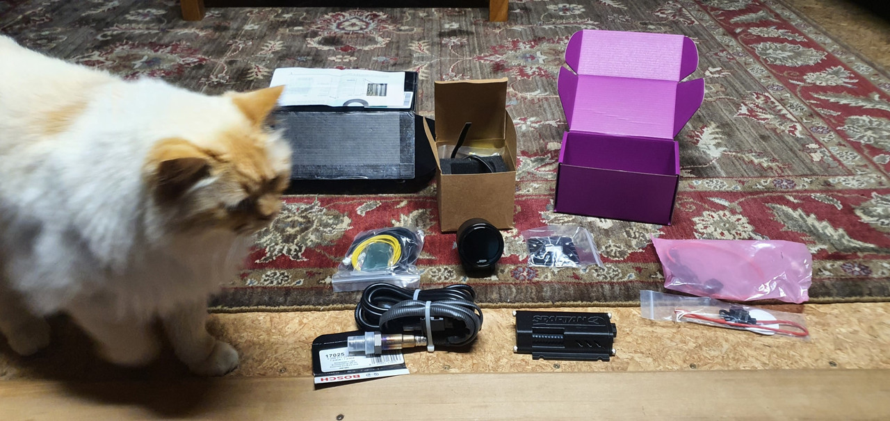
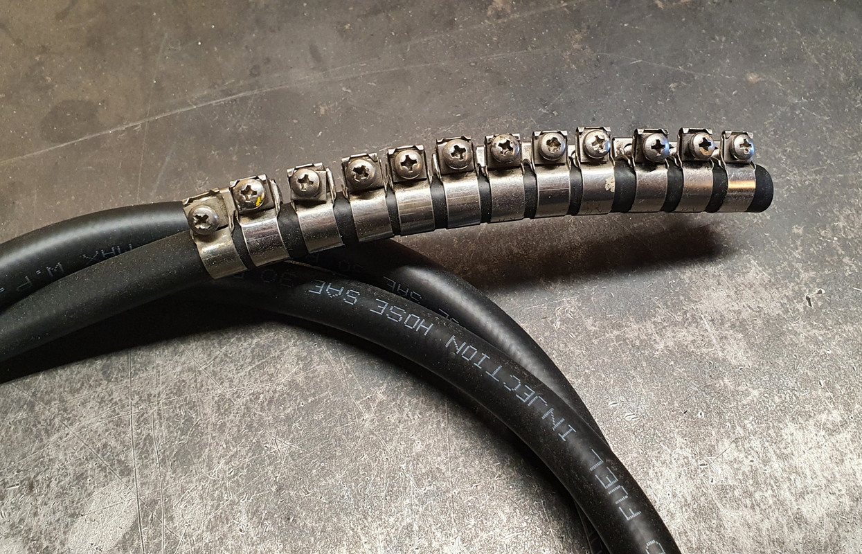
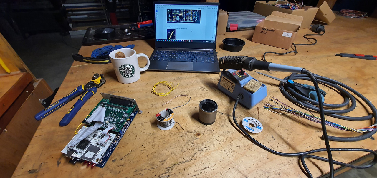
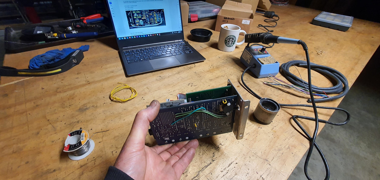
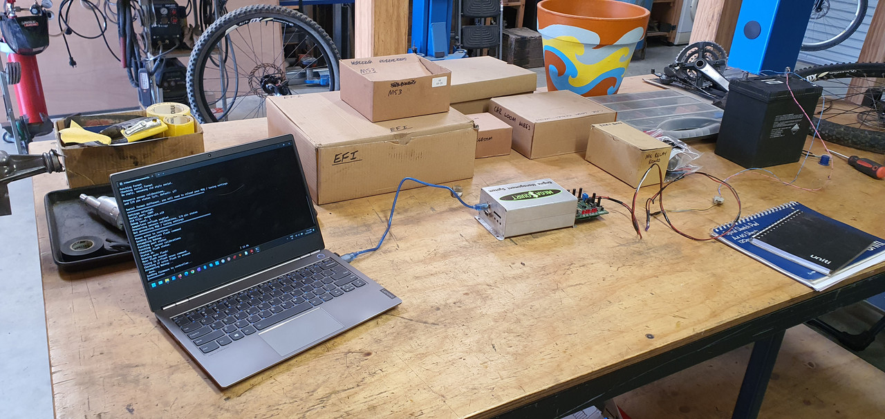
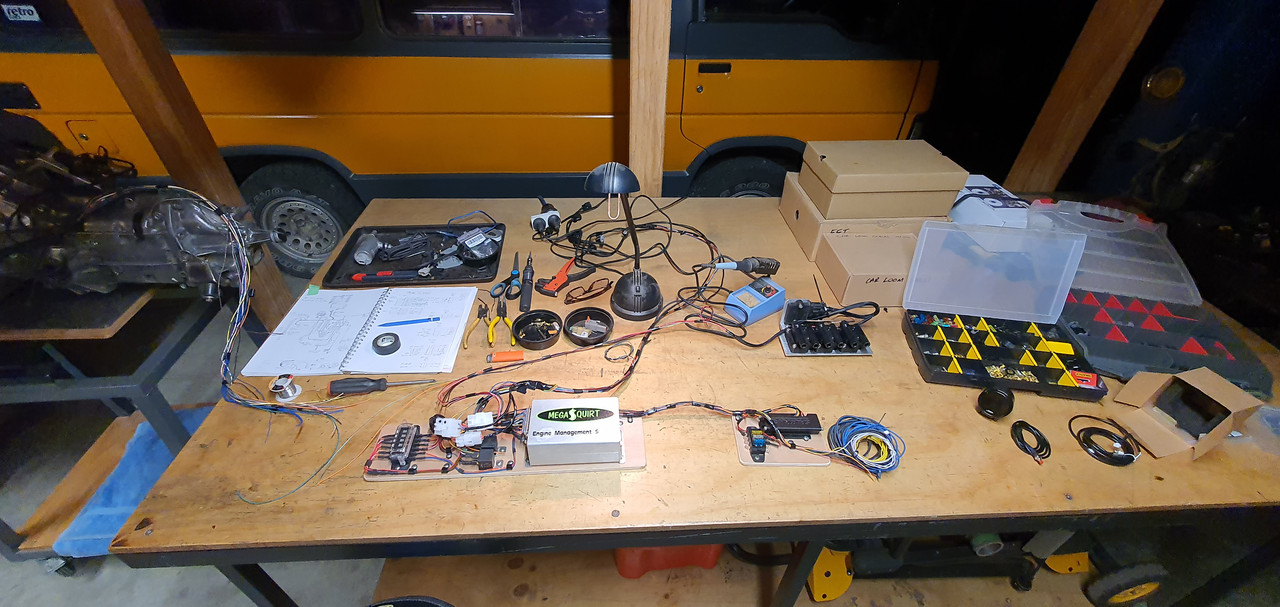
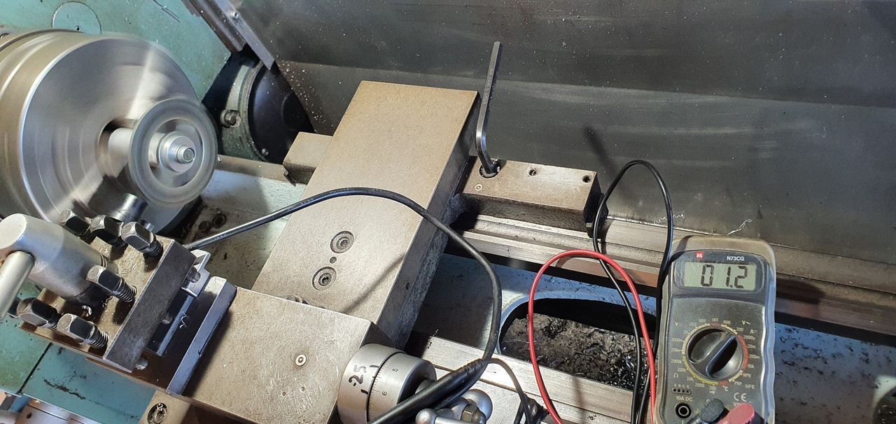
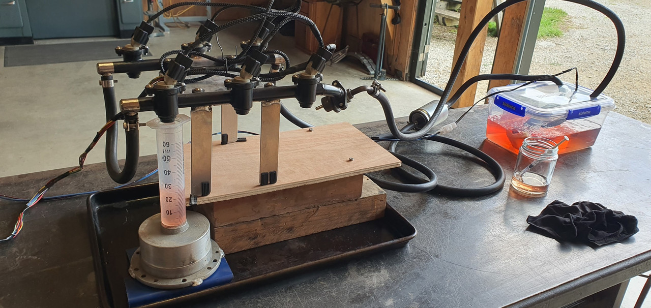
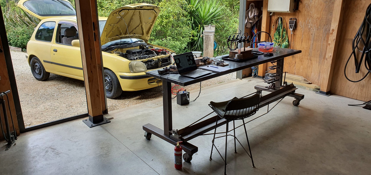
I finished what I needed to on the loom to enable testing of the injectors. I had made a simple little alloy jig that I could bolt the two rails onto and it sat high enough that 6 matching jam jars could sit below. We set this lot up on the big mobile steel bench and rolled it down to the front of the workshop near the entrance just in case it all goes a bit wrong. Set the ecu up along with a little 'ignition' switch and starter button for later testing of various engine sensors/ test running.

Image

Image

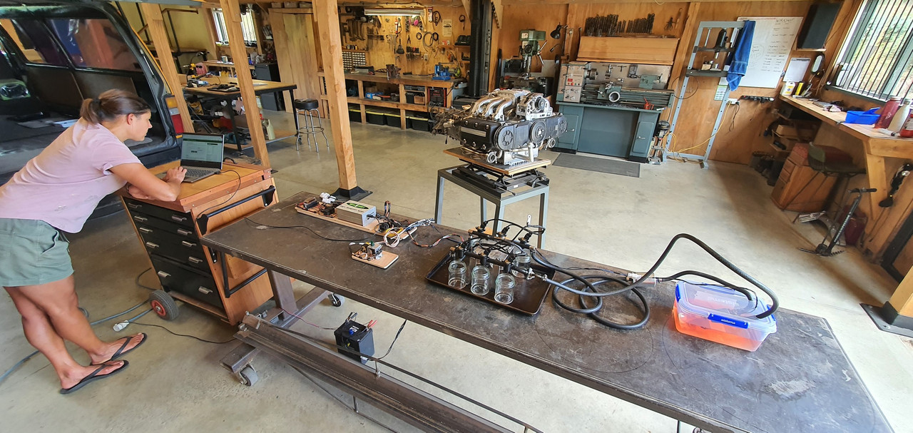
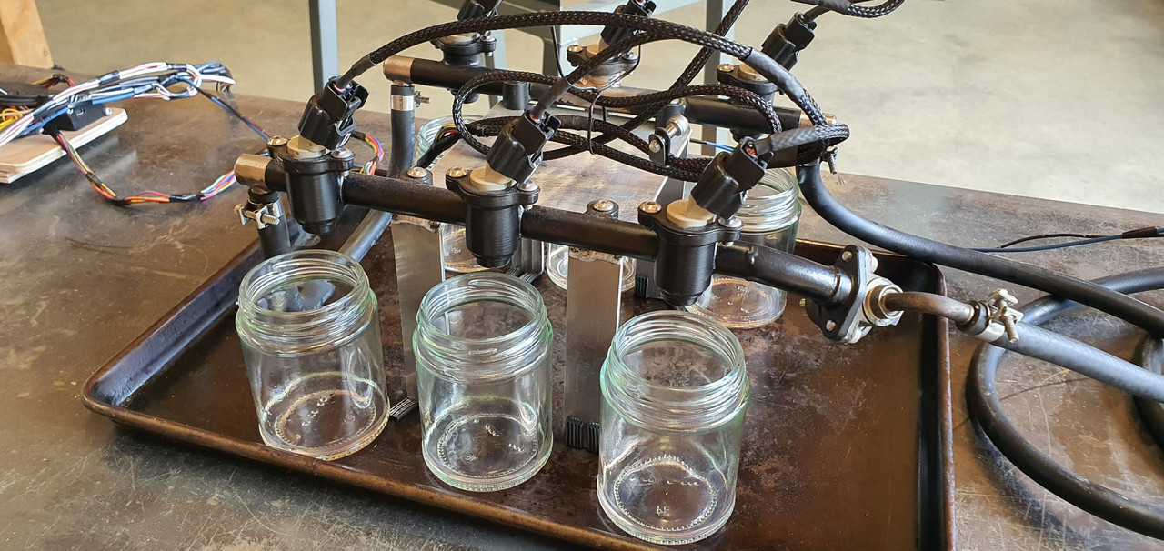
The tuning software that megasquirt uses, Tunerstudio, has a good set of testing programs built in including injector testing. Started using that and as soon as the injectors primed and started squirting we found a tiny leak.

Poos.

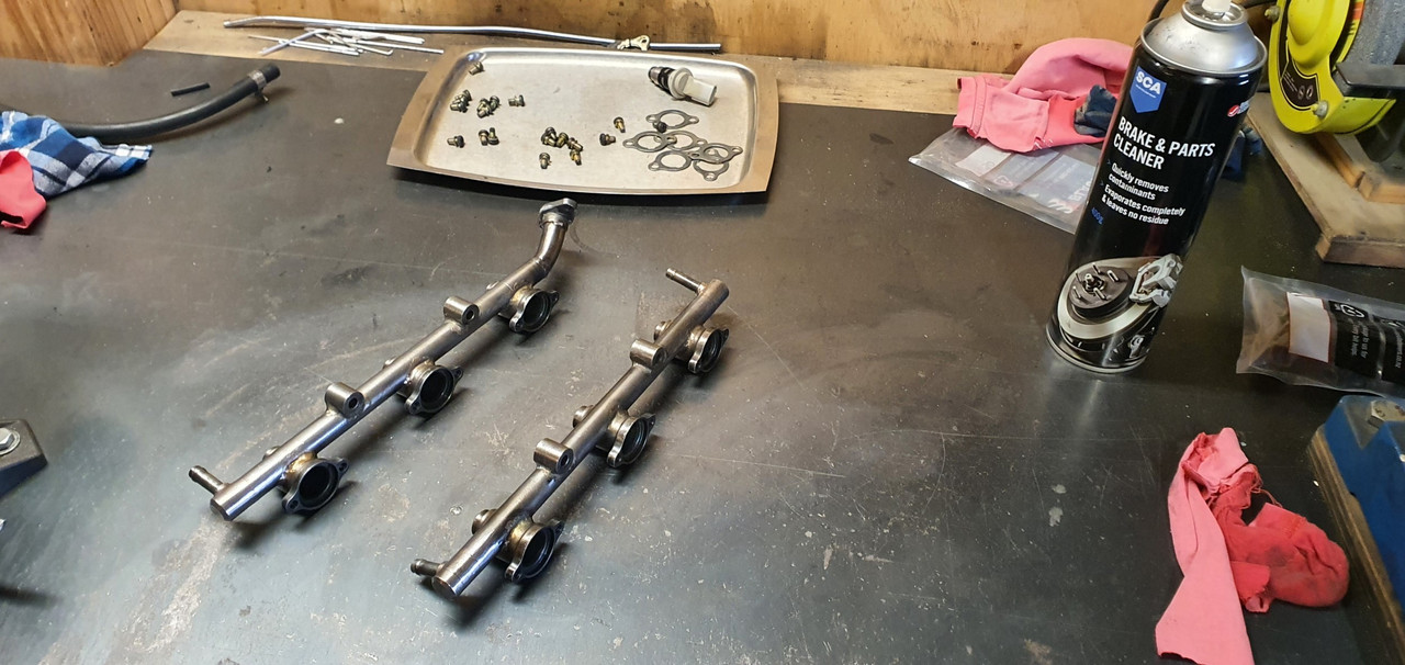
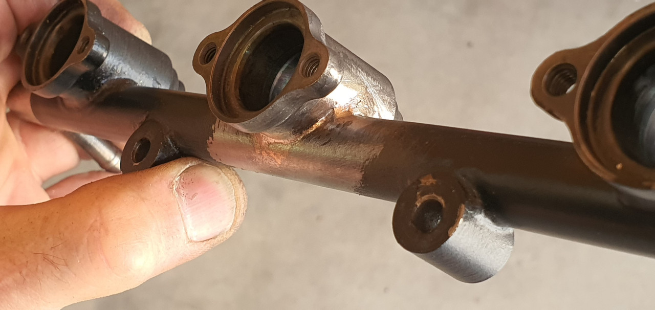
My home made rails were brazed together and there was one teeny bit the bronze hadn't flowed into leaving a tiny pin hole that let out a comical jet of fuel. Glad I tested them now.

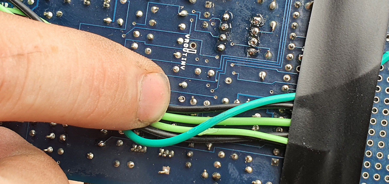
Here under that lovely layer of carefully applied epoxy black...
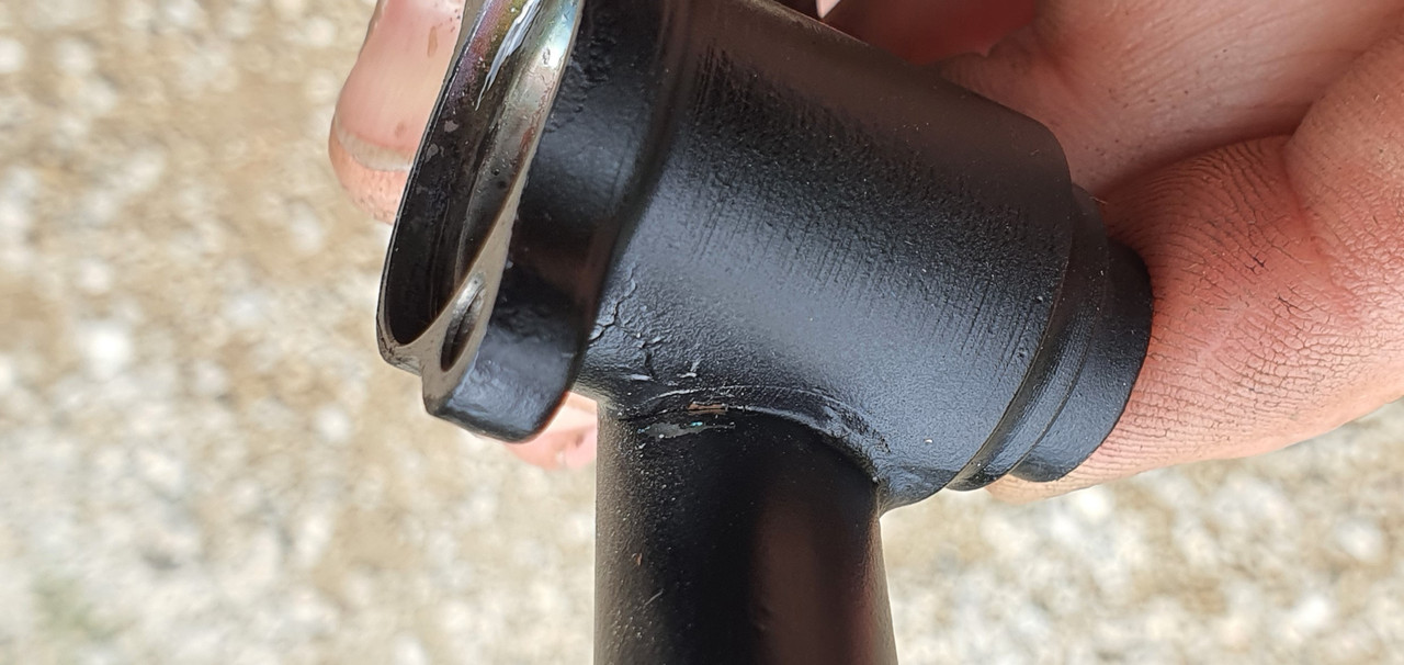
Image

was a tiny hole..

Image

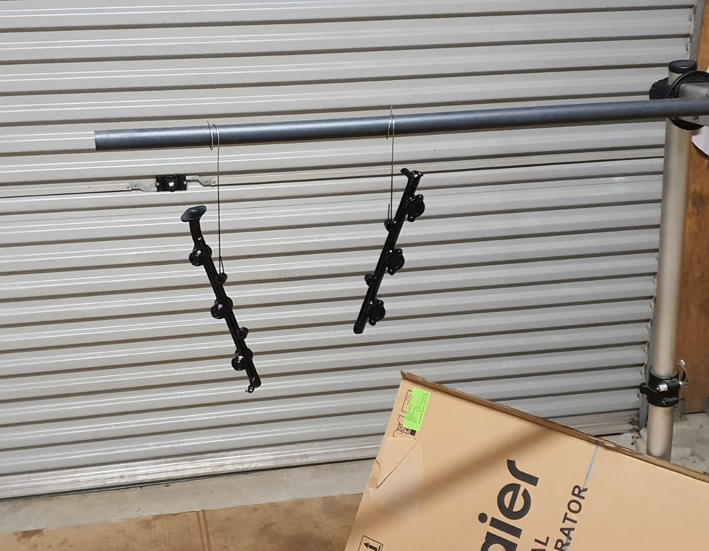
So out with the oxycet and I brazed it up.

Image

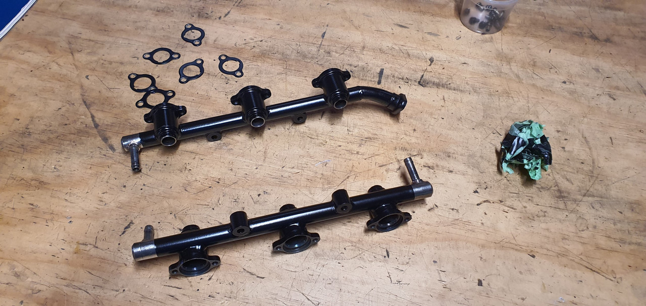
Then re-tested the setup. No more leaks :)

Image

We ran through a few tests and made notes on fill rates at different opening times/frequencies etc etc to work out the injector dead times. Not a crucial thing to do but since it was setup as such it seemed rude not to. The battery I had was a bit tired and my charger couldn't keep up so I installed a larger Nissan charger at the front of the workshop. This also meant the testing was being done at a realistic voltage you'd expect to see.

Image

Happy the injectors were all matched and meeting the factory Nissan specs I packed all the stuff away.

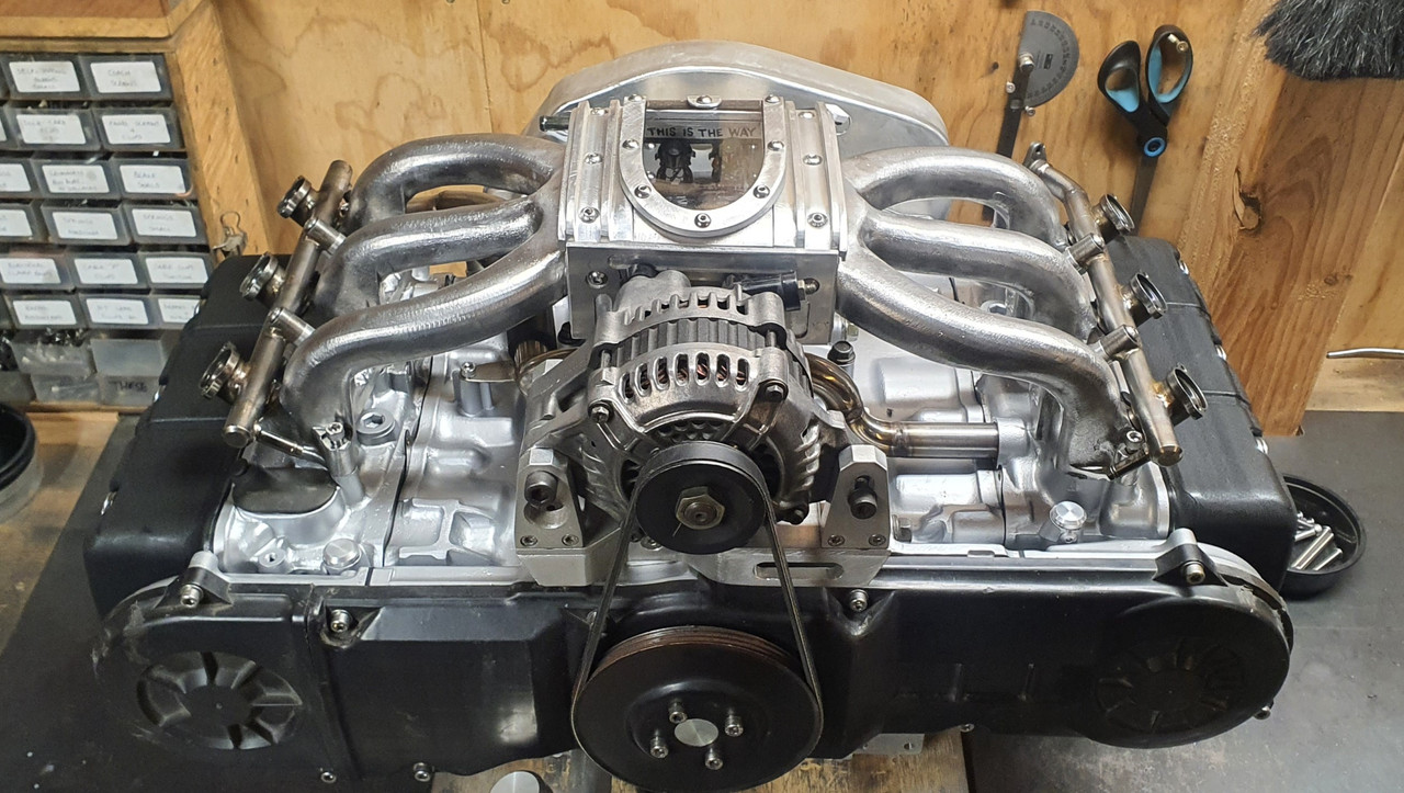
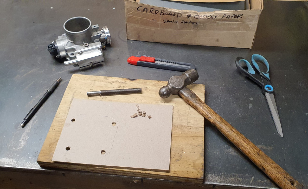
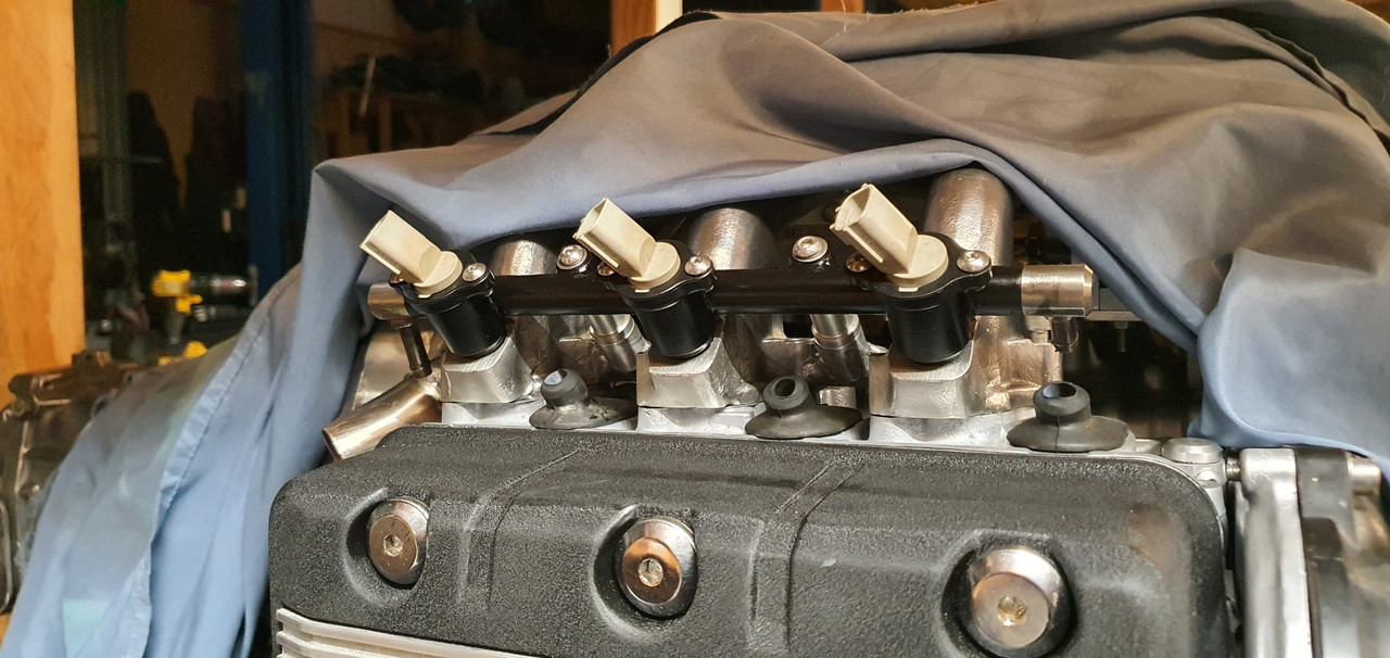
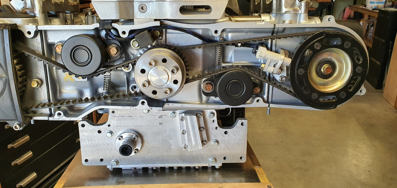
Then I fitted the inlet manifold gaskets and bolted the inlet in place on the engine, followed by the rails, with the repaired bit hand painted with epoxy as best I could to match.

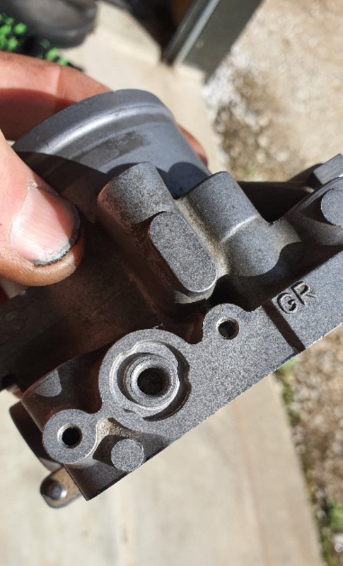
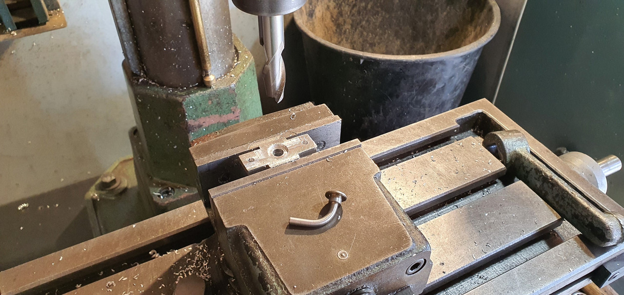
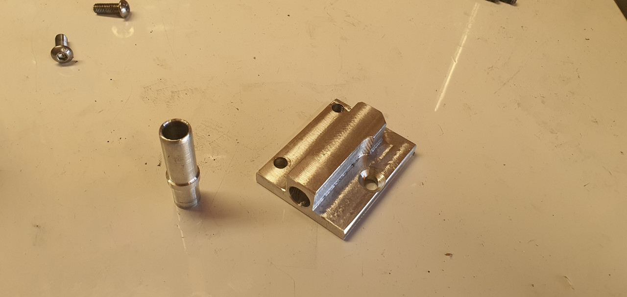
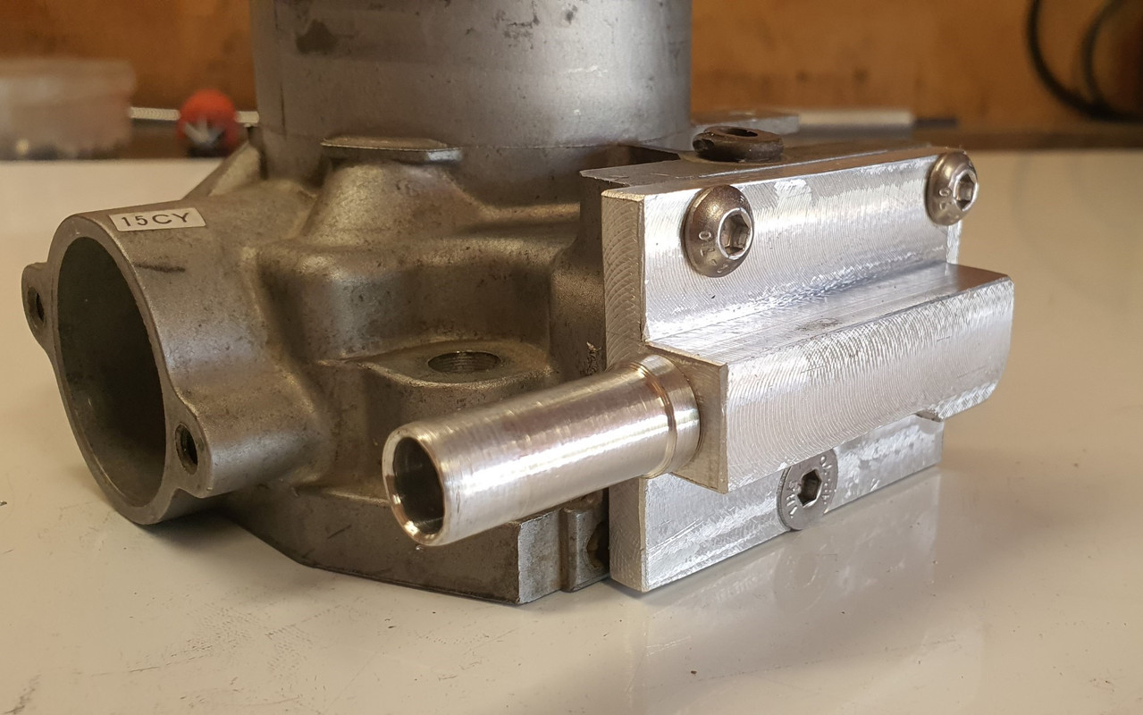
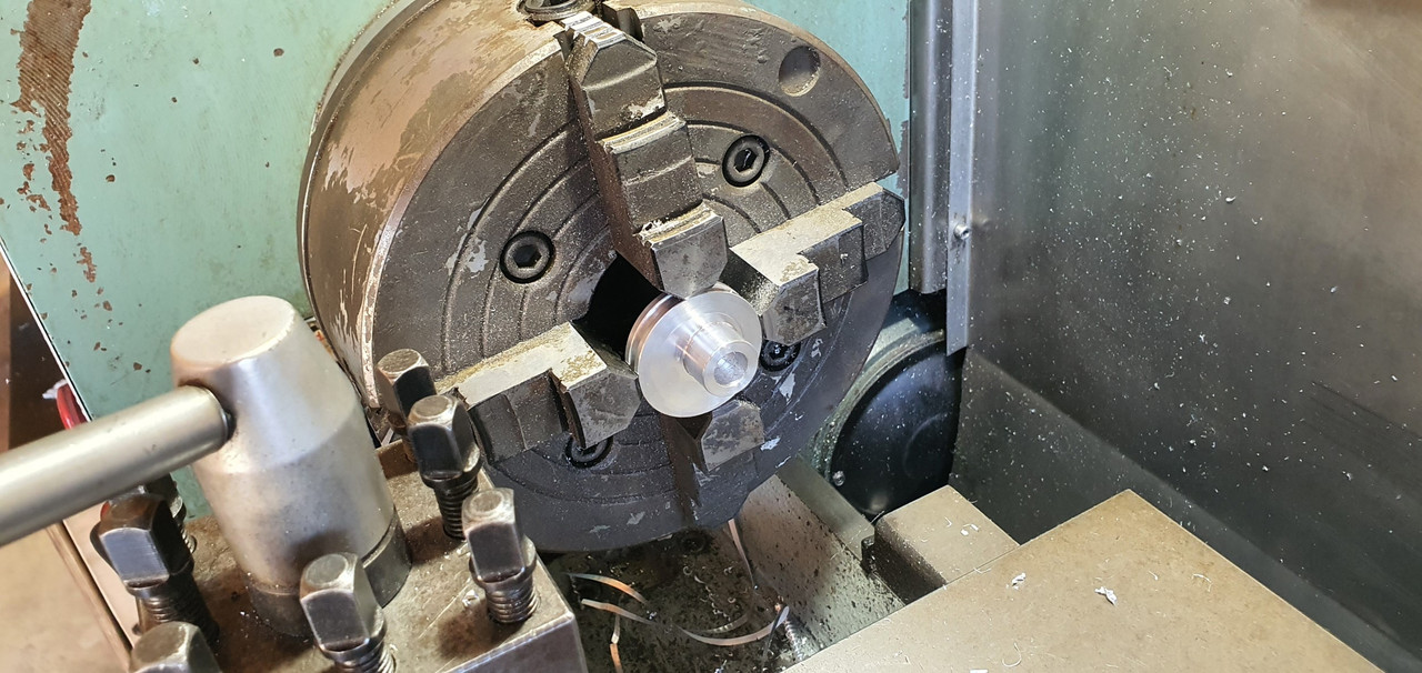
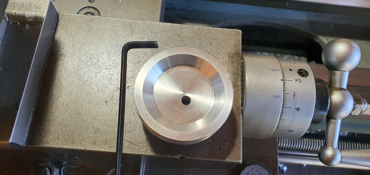
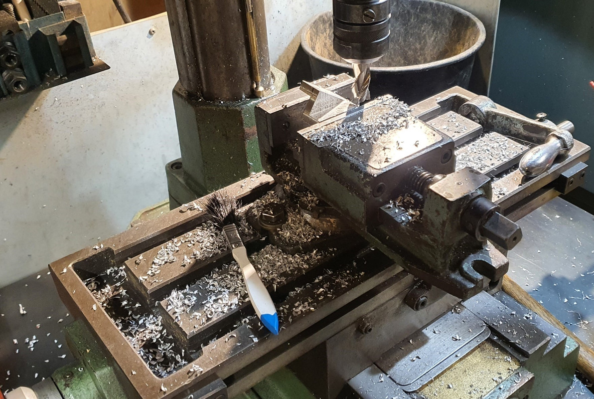
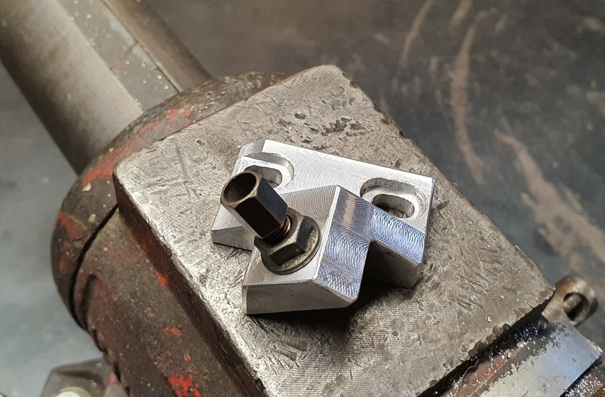
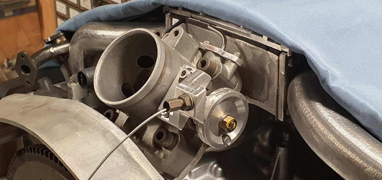
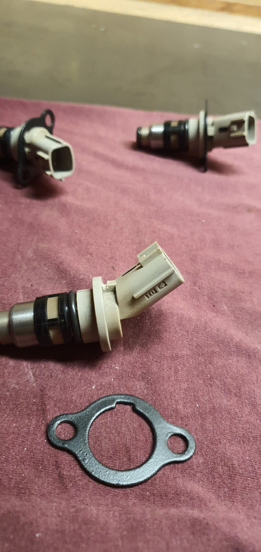
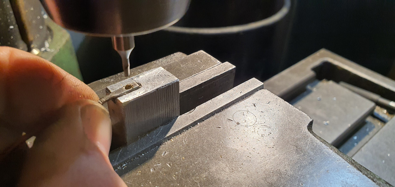
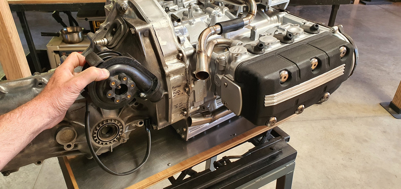
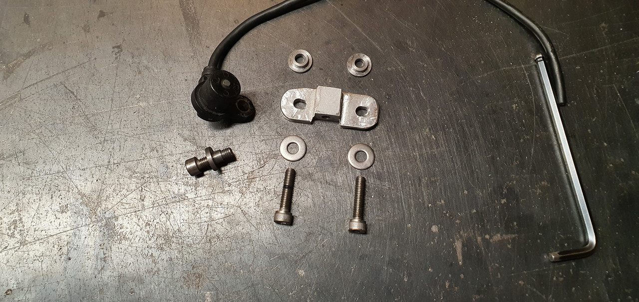
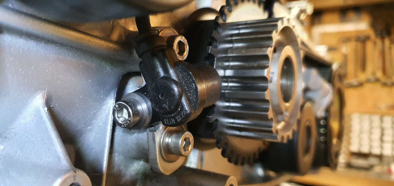
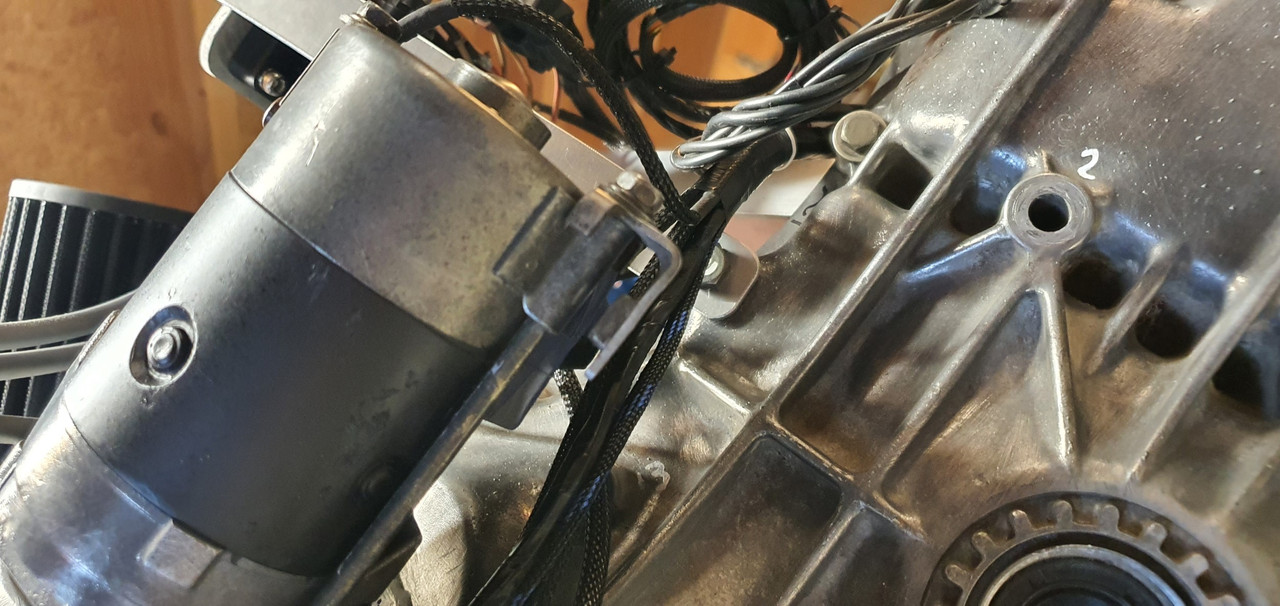
Next job to finish was the Bosch style idle air control valve. It had far too big in and out bosses so I machine up some stepdown parts to suit a more sensible sized tubing. I needed to mount it somewhere out of the way, safe and not on view because its not very pretty. I spotted a handy bracket on the bottom of the starter motor that has a threaded hole. Perfect! I made a little P clip to suit mounting the iacv.
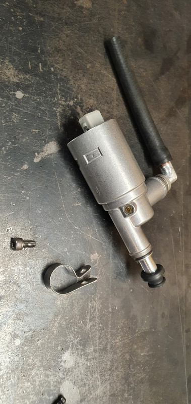
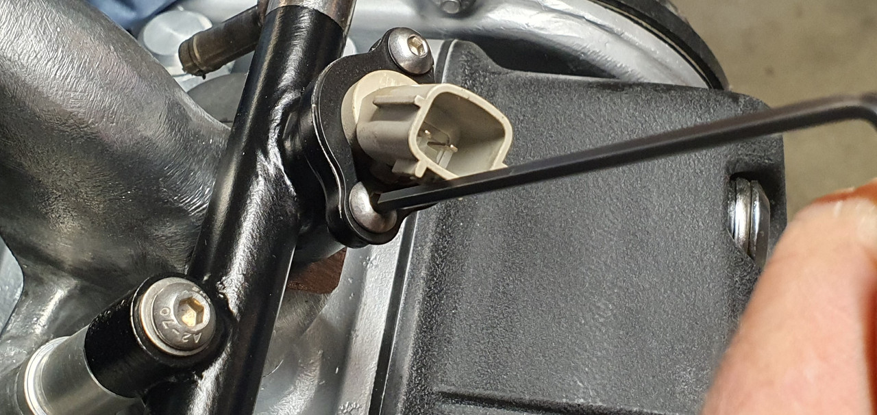
Image

which bolts here..

Image

Like so...

Image

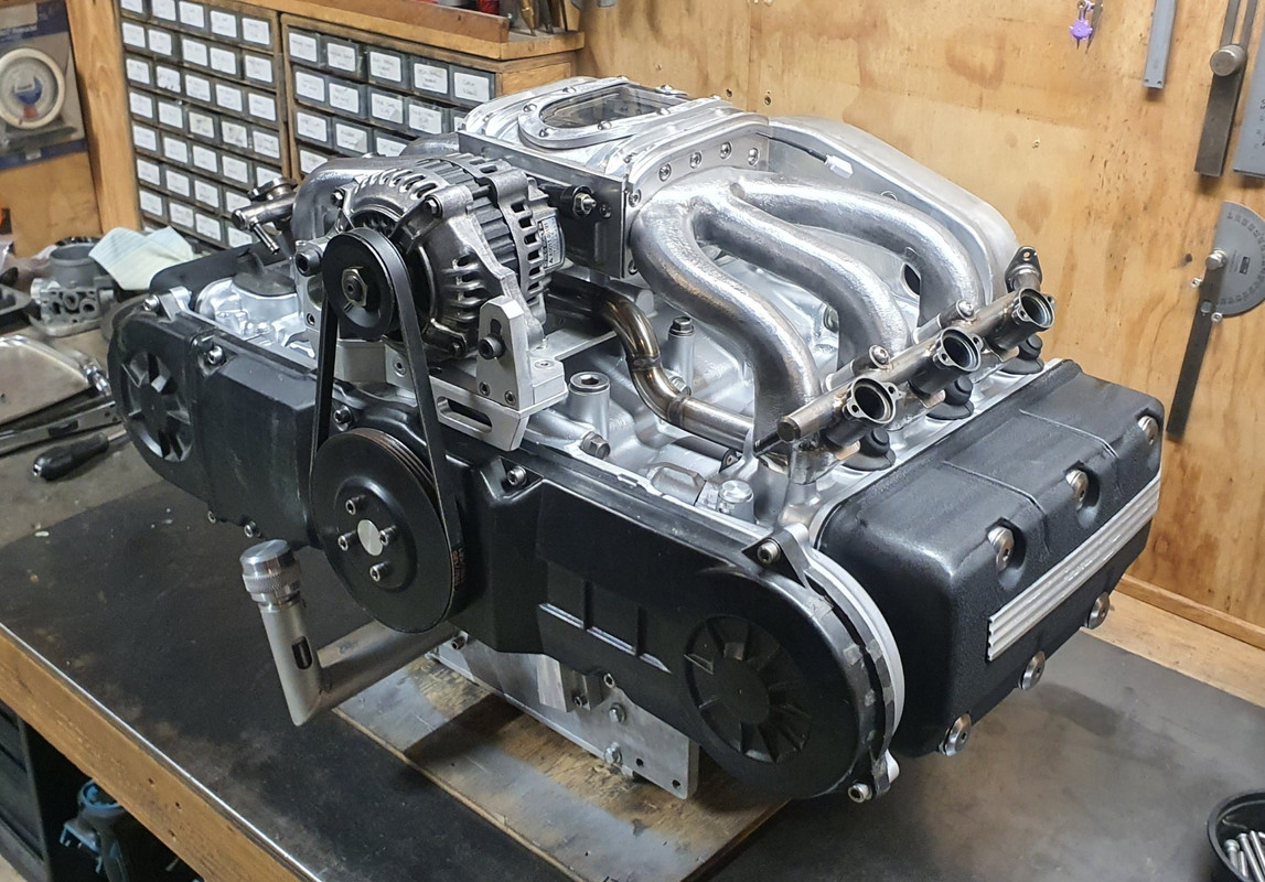
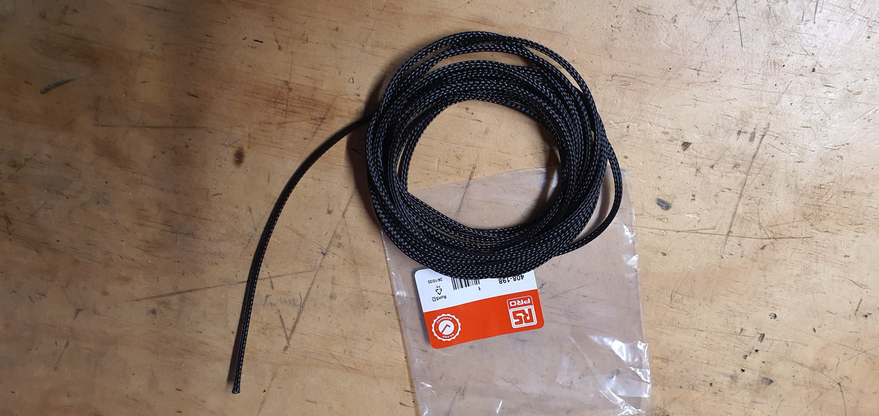
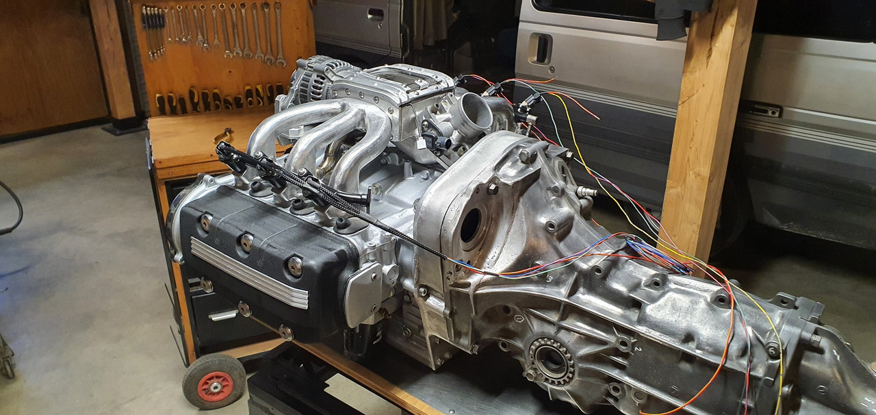
I did some more plumbing to suit and after a few last little bits of wiring the engine was about complete. I pod fitted the filter I'd bought a while back directly onto the throttle body but it will actually end up remotely mounted in a cooler spot. I was just waiting on some posh ventilation hose to arrive.

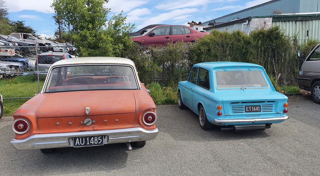
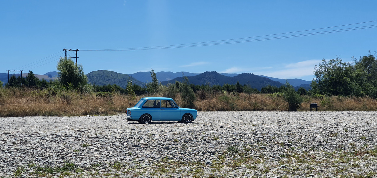
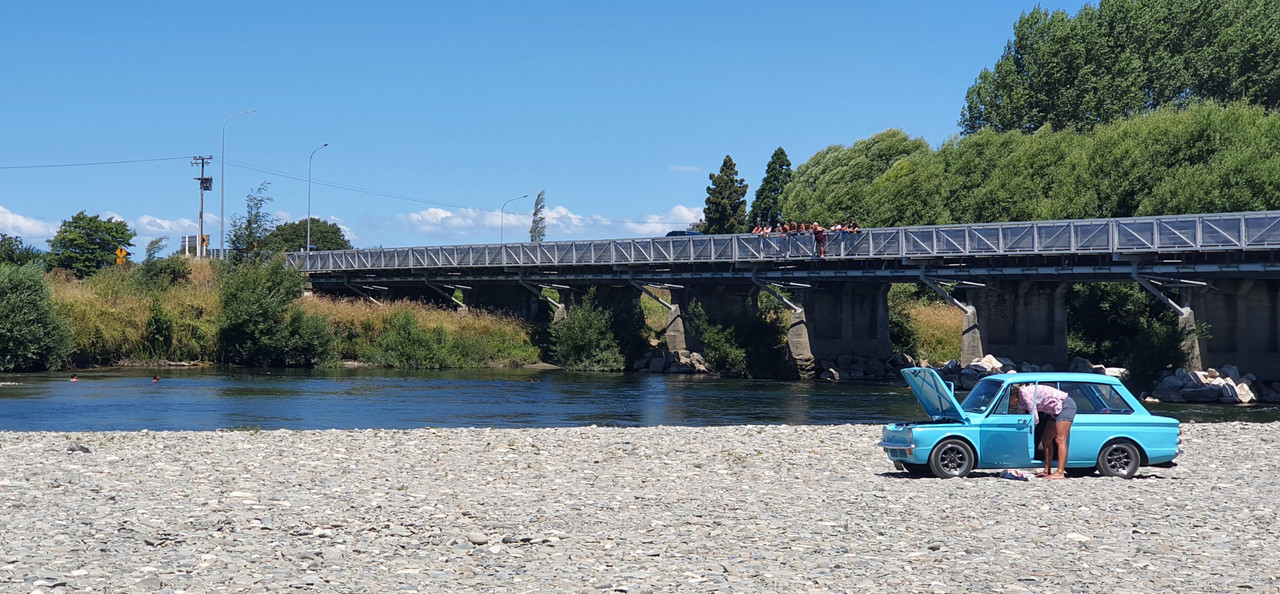
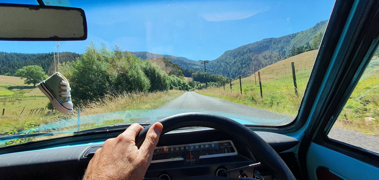
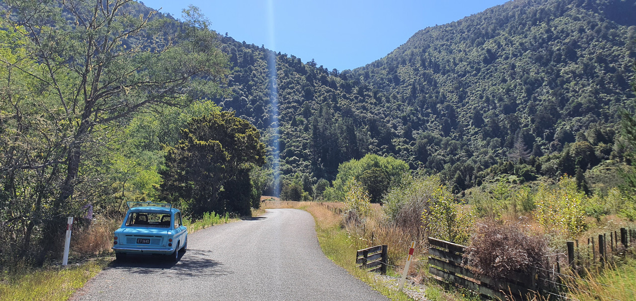
The Imp got a fresh wof and we took some pics of it when down at a local swimming spot near Motueka. It looked neat on the river stone so I took some pics..

Image

Image

Went hooning up a local valley to get wild plums..

Image

Image

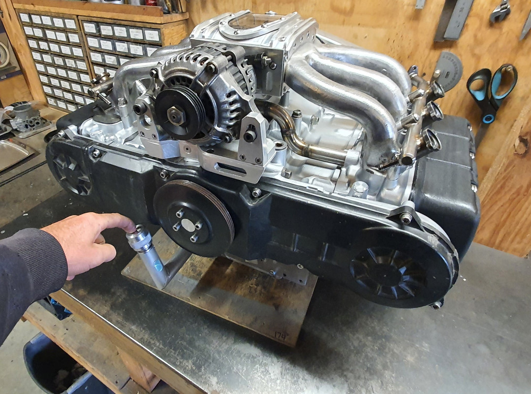
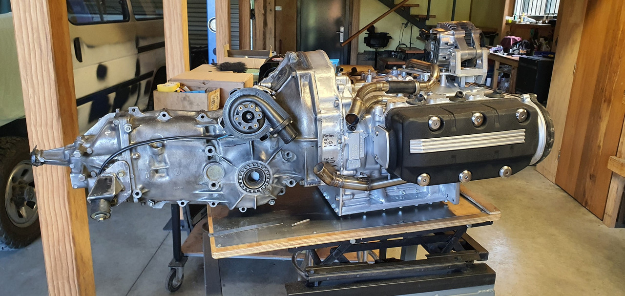
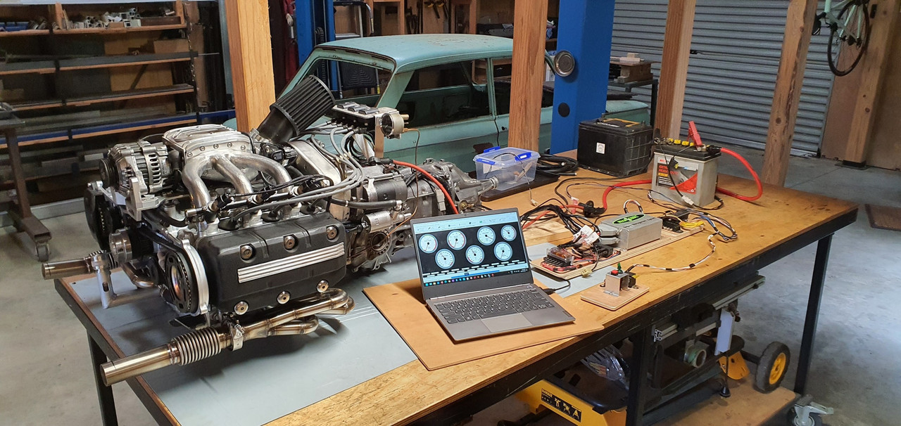
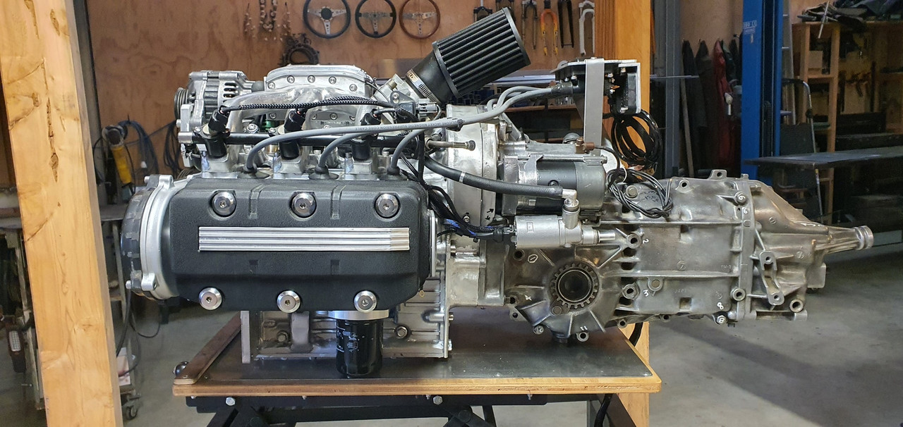
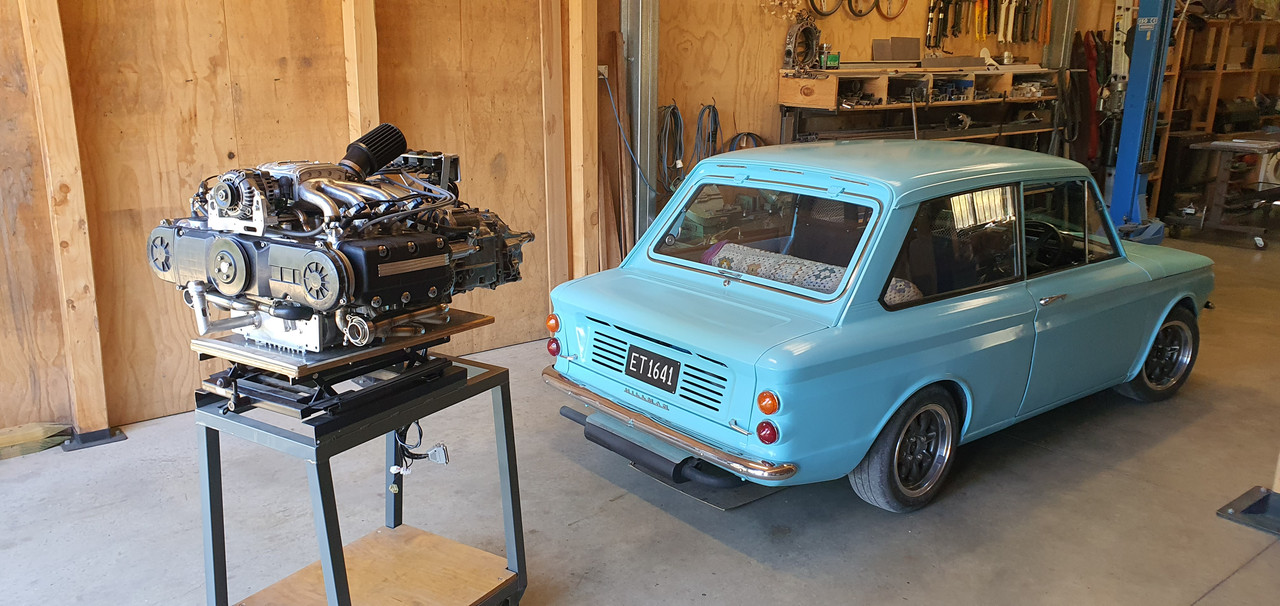
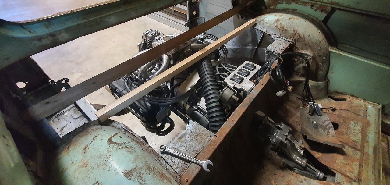
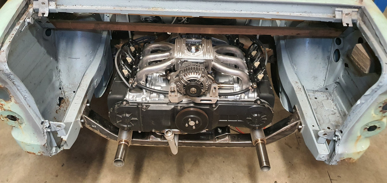
Got home and snapped some pics of the engine next to car. The perspective makes the engine look huge...

Image

Image

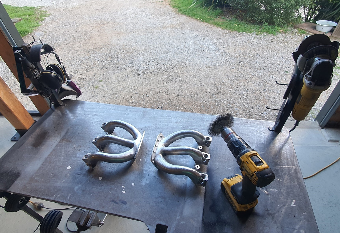
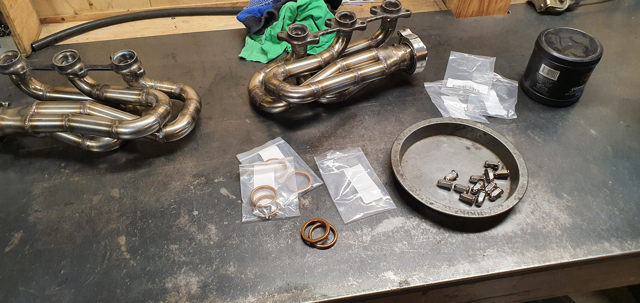
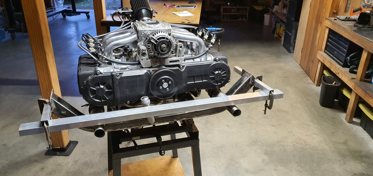
Next stage was to bolt the exhaust headers in place properly with the new gaskets and special nuts I'd bought.

Image

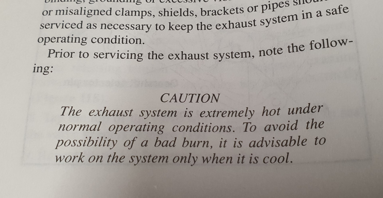
But before playing with exhausts always be aware of the potential dangers, as so carefully pointed out in the workshop manual !...

Image

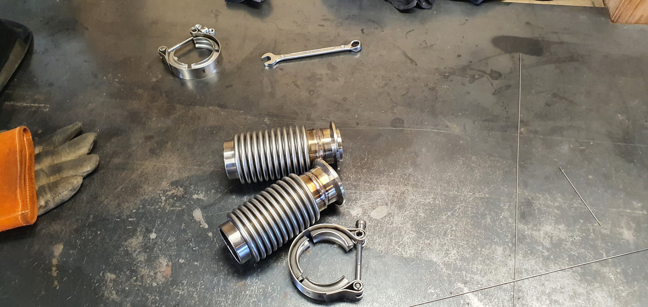
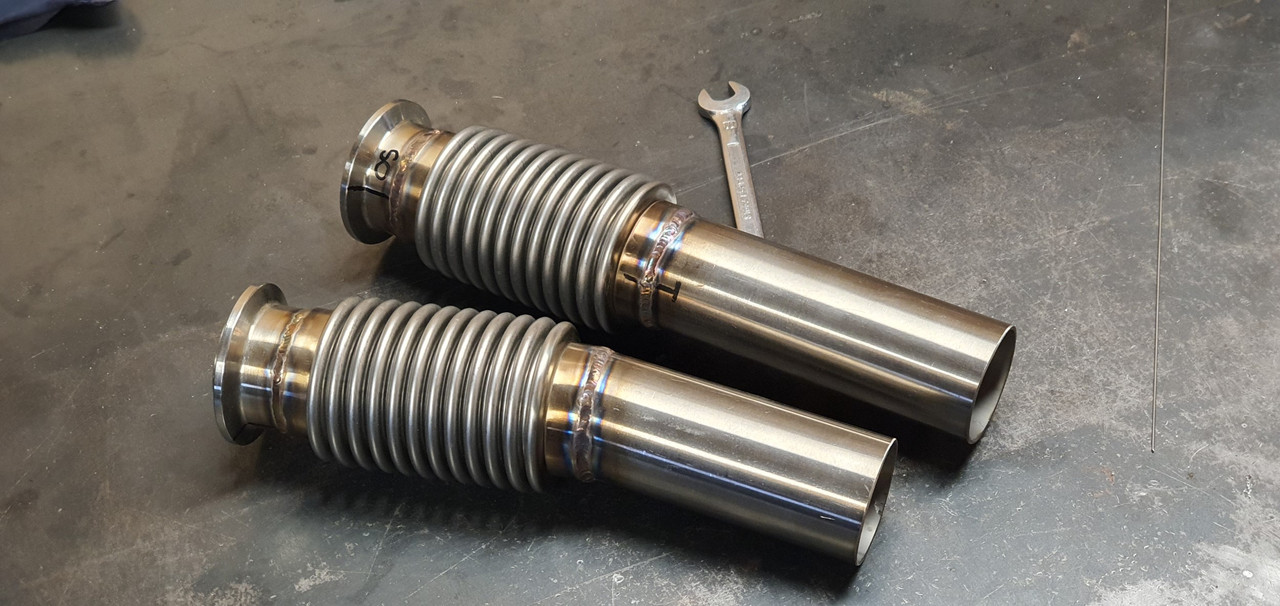
Manifolds bolted up fine but a few of the nuts are awkward to get started as its tight on space around the header pipes. Next parts in the exhaust chain was the flexible joints.

Image

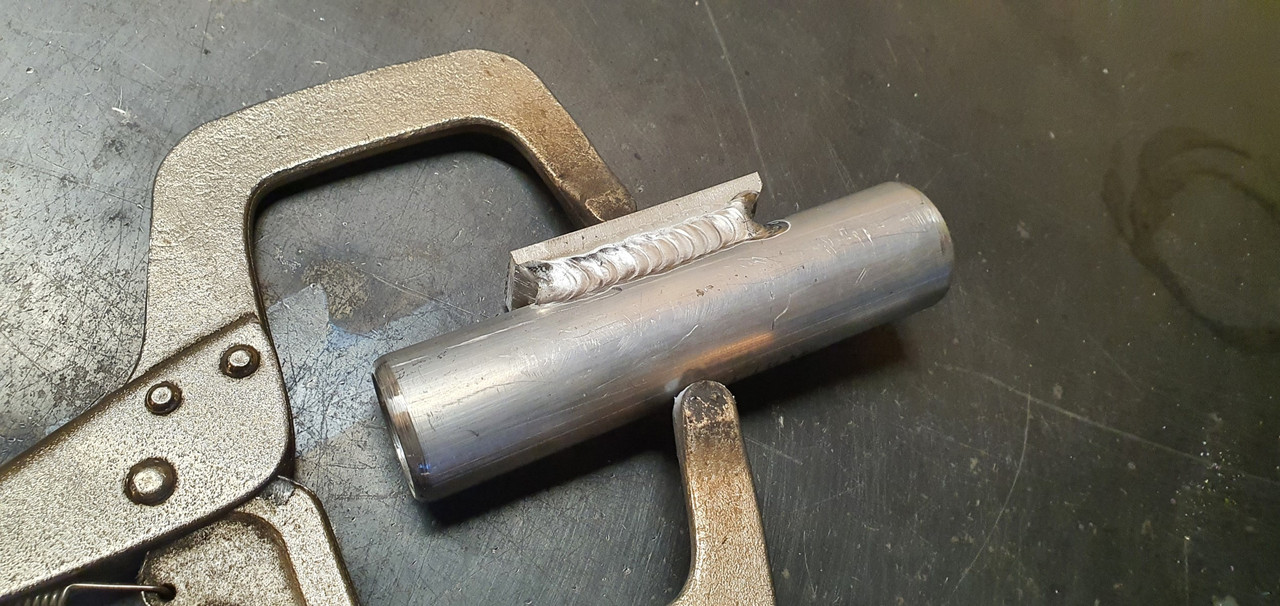
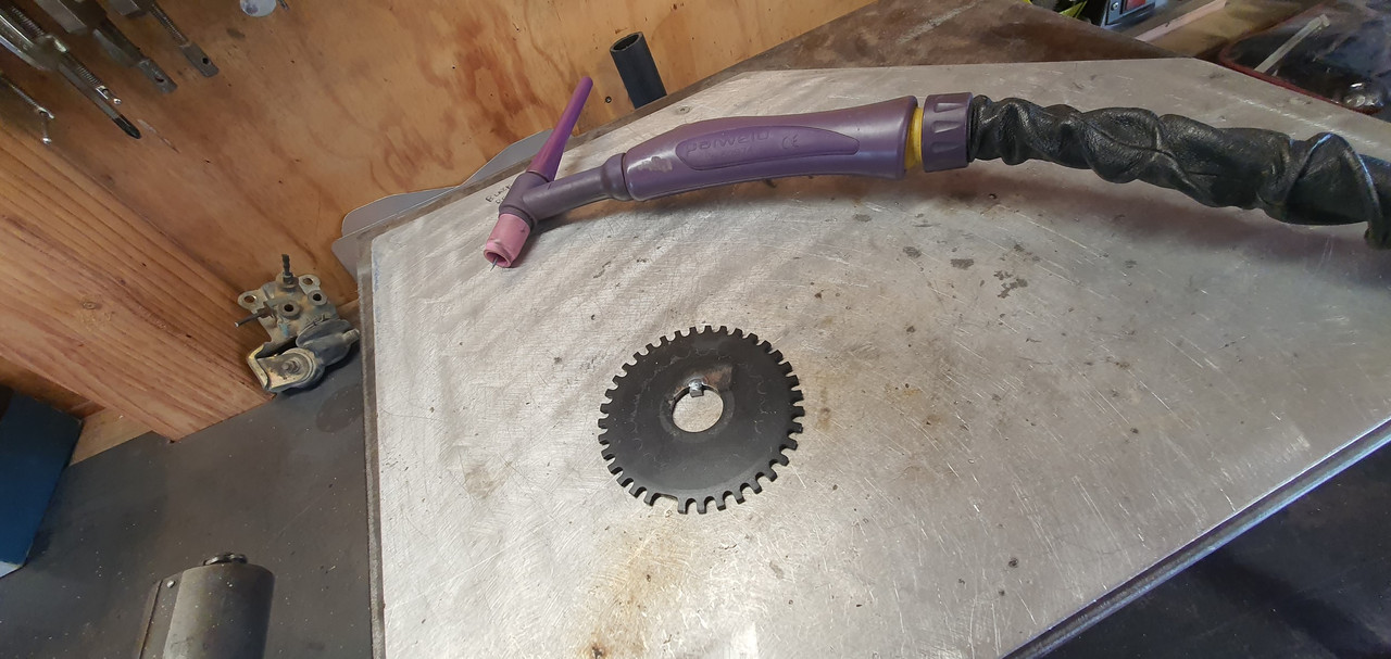
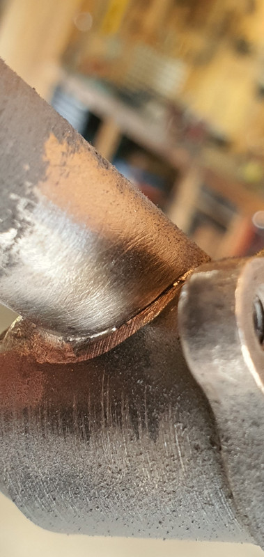
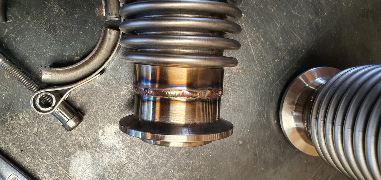
My welding was improved a bit by wearing some reading glasses. :) I guess I just have to accept that aging thing and embrace the power of +1.5 because now I could actually see what I was welding. Its still not instagram weld porn but it'll do for this project

Image

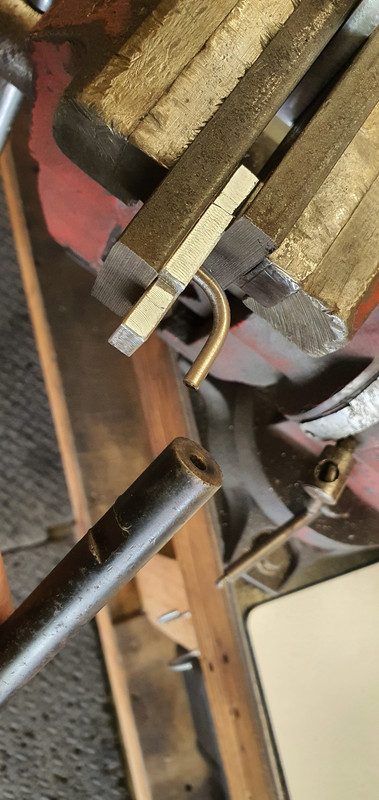
Bolted the cross member in place and with a bit of alloy I was able to check the heights to weld the next sections at.

Image

Unfortunately I must have fabricated the LH manifold out of line and I have ended up having to weld the secondary pipe at an angle to make sure the outlet heights match. It wont be easy to spot when its on the car, with a exhaust box hiding them. But I know its there...:doubt:

Image

Or maybe I don't bother with a single large tranversely mounted silencer and just run a couple of old dumpy mufflers...

Image

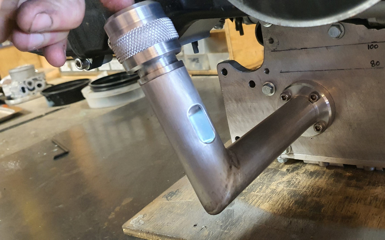
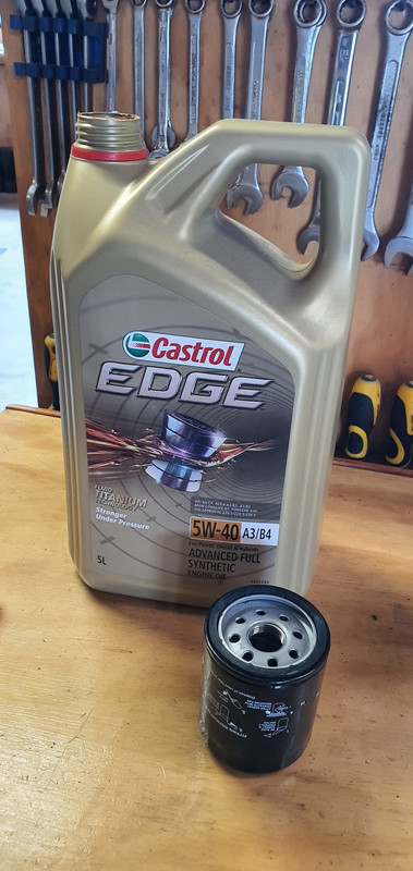
I was now at the point I could fill the engine with oil and test the oil system. Quite a while back I bought some quality oil when on sale..

Image

I filled the filter up first and then carefully filled the engine. Up until this point I had no real idea of exactly how much my resized sump would take before it got to height I wanted it at. I'd done some basic sketches and napkin formula and I knew it would be more than 3 litres. Hopefully more than 4. It almost took 5 litres to get to the halfway point on the sight glass and that will drop once the oil pump primed up and filled the oilways.

Cool. Great news then. I'm really happy it'll have a decent amount of oil in there.

Now remember back to around the end of December 2021 when I wrote this...

"Lastly I needed to bolt the sump cover in place. I had to think carefully about bolt placement for sealing purposes and get the bolts square. This sump plate is going to have to be sealed well because there is no usual high sided sump like most cars. Hence I built it rigid to help against flex. Good quality sealant will be the order of the day*

*It will leak. Its a British car. Its destined to leak."


Well then. Guess what. It leaked! Ha.

Image

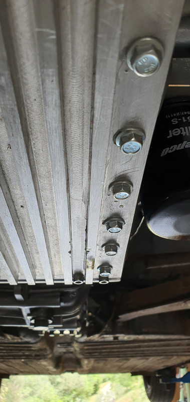
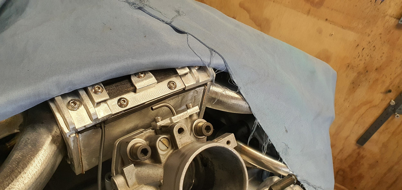
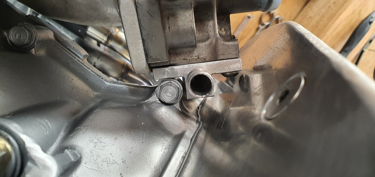
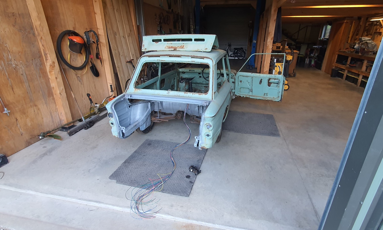
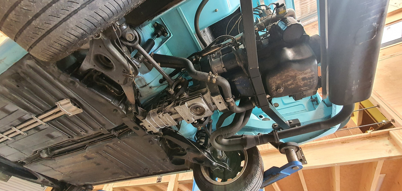
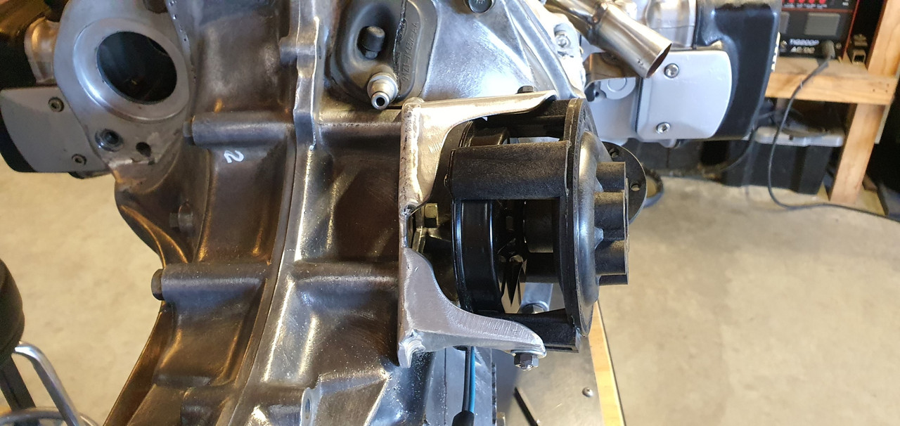
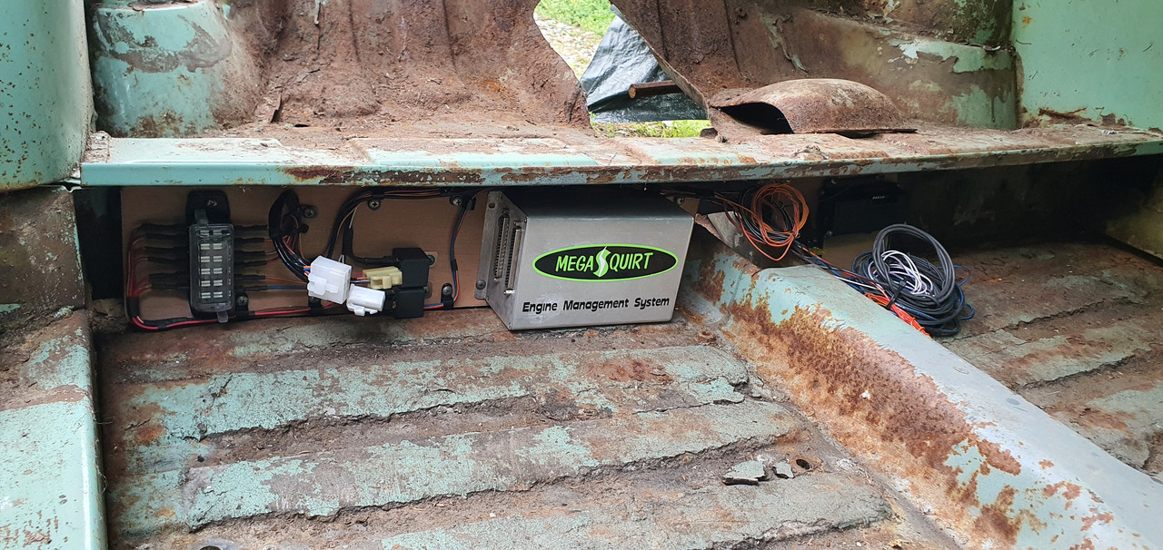
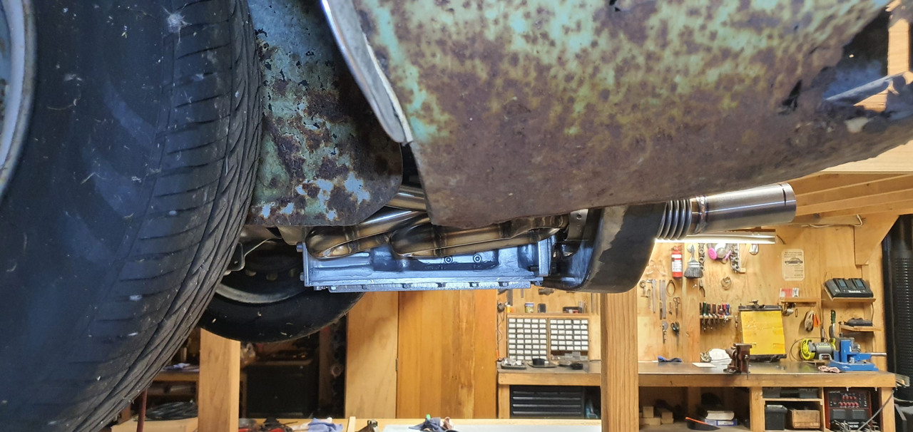
Just after patting myself on the back at having a great sump capacity the level started to drop and was leaving a good puddle on the engine stand top. So Hannah helped me move the engine so I could drain the sump and then I mounted the engine/box assembly into the spare imp. On a positive note I was chuffed with how quick and easy it was to bolt up in place by myself - all of about 5 or 10 minutes. Engine in place and with the car up in the air I took that above photo. I had a good idea where it was coming from and wasn't feeling to glum ( no even a single toy was even lifted from my cot)

I unbolted the sump plate and found the hole...

Image

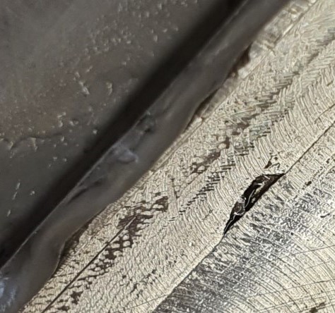
When I was making the sump plate and milling the slots in the plate it had shifted out of line without me spotting it had done so until too late. I had to weld up the resulting mess and re-machine that area. I thought it was fine but I'd missed a tiny pinhole, maybe exposed when I machined the inside of the plate out to take some weight off it.

The plate got a good clean (that threebond sealant is tenacious stuff! ) and I fixed the hole with a dollop of JB weld.

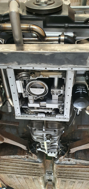
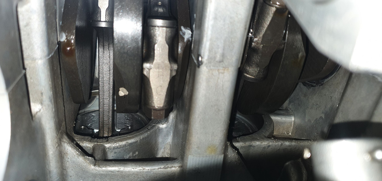
Took some pics of engine from below with its innards exposed..

Image

Little pistons...

Image

Bolted the sump plate back up, waited till the following day and refilled it. This time no puddles.

Yay.

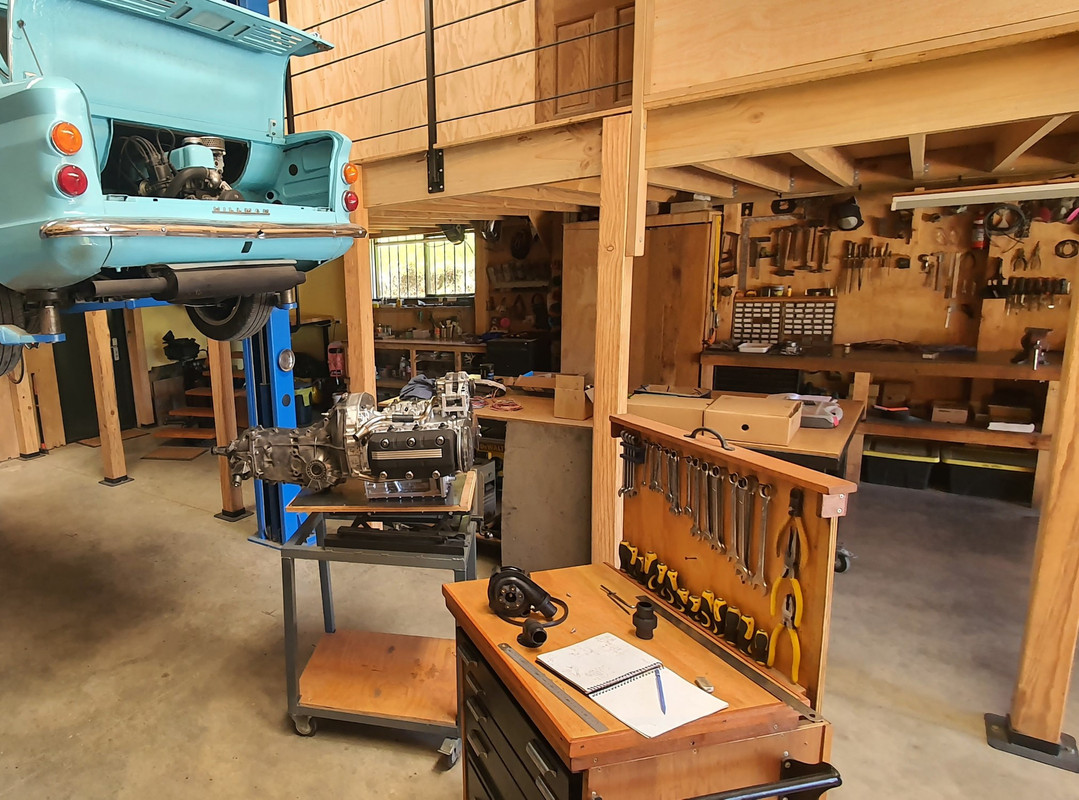
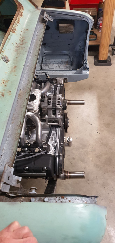
While the engine was bolted into the spare imp I took the chance to double check measurements and clearances. It was all looking good and I was very happy that I had placed things ideally, especially as most measurements were taken in awkward areas by all sorts of various ruler/tape measure/level balancing acts. The coils, just mounted on their makeshift bracket for bench testing, are actually almost bang on in the right place and only sitting a touch too high. The filter hose will just clear the underside of the parcel shelf and there's heaps of room for the remote filter..

Image

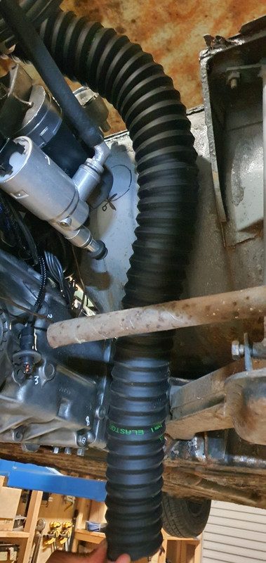
Hose (turned up the day before) ..

Image

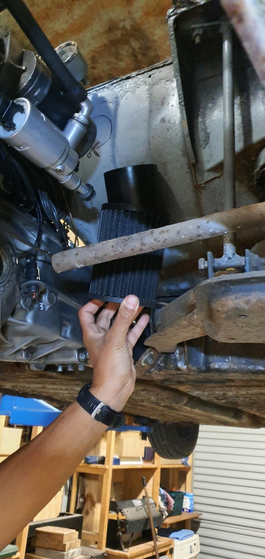
Hannah's hand holding filter roughly where it will be mounted to the bulkhead...

Image

Lots of room out back between engine and where the removable rear valance bolts in place..

Image

Image

Image

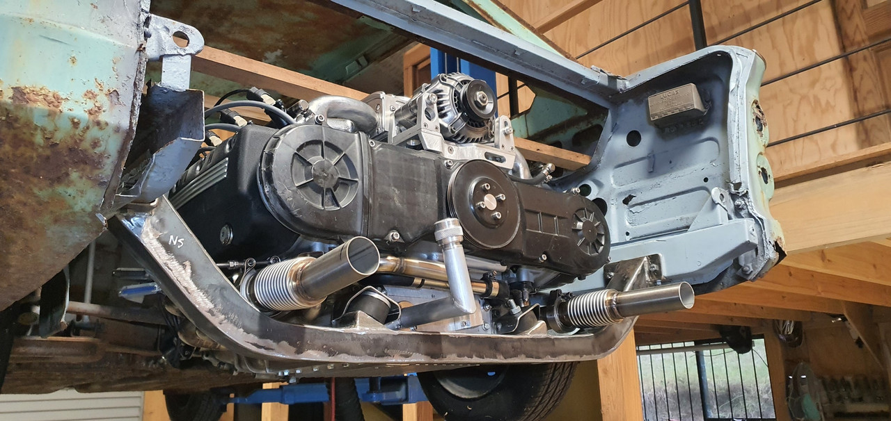
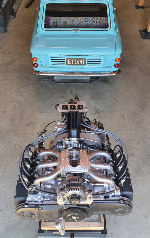
and lastly, the 'Mandalorian spaceship' will not at all be hidden by the rear parcel shelf ..

Image

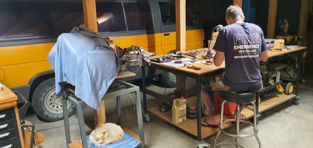
Engine is now out and back on the bench for more 'bench testing'...
yoeddynz
DDK Fanatic
Posts: 54
Joined: Wed Feb 01, 2023 9:02 am

Re: 1965 Hillman Imp soon with flat six from a Honda

Post by yoeddynz »

​Bench testing continued.

The sump was now holding oil. Phew. I fitted the old smiths mechanical oil pressure gauge that was originally fitted in the imp race car. I mounted the gauge to the temporary coil stand. With the engine cranking over it was seeing about 20 psi. The oil level would drop in the sight glass and after a minute or two it would be back to the old level. I was happy with this.

Next on the list was to check the idle control valve was working. Its a 2 wire Bosch style pwm type unit. Very common, simple, reliable and hence used often in megasquirt installs. Its basically a rotary valve that is opened against spring pressure by a solenoid windings when current passes through them. The ecu earths its ground wire in a series of pulses, the quicker the pulses the more it stays 'open'. Simple as I thought.. but.. this is where I discovered that I had bought one of the units that is actually 'closed' at about 30% duty cycle. A failsafe on cars that use these for closed loop idle control (aircon/powersteering/epic sound systems etc etc) If the valve fails then spring pressure actually takes it to a slightly open state so the car cant stall.

But I'm only using the valve for open loop at start up. So when its closed I want it to be closed. Luckily I was able to pick out/burn/pick out/burn/pick out the tough as epoxy that was holding the valve stop adjustment screw in place. I wound the screw in until the valve was closed with no power. It still passes a tiny amount of air but its much better. I'll manually adjust the idle bleed screw on the throttle body to get the fully warmed up idle where I want it when that time comes.

Which was going to be soon I thought! Next thing to check was that the crank angle trigger wheel VR sensor and the camshaft half moon hall sensor were both putting out satisfactory signals. Opened up the composite logger on tunerstudio expecting to see nice clean signals.

Image

But there was nothing. My heart sank. Oh here we go..

I took off the cover on the main board plug and checked the connections there. I then popped the volt meter, set at AC volts, onto pin 1 and 24, wound the engine over and got about 2.0 volts.

I don't have an osillioscope and only have an old megastim 2.2 testing unit which won't create the required rpm signals I needed for testing.

I wasn't quite sure what to check next so I started a thread on the megasquirt forum. Got some bits of advice but in the end I rang a mate who lives about an hour away who has a lot more knowledge with megasquirts and has helped me out in the past. Organised to go see him the foloowing day. In the meantime I checked the hall sensor. I had never been able to find confirmative details on the polarity of the hall sensor even though it was a really commonly used unit among many a citreon/fiat/renault etc. I finally found a factory service manual online for Fiat ducatos which had a pin out of the sensor. Turns out I'd got my polarity wrong and after swapping the wires around at the hall sensor plug I now had a strong clean cam signal.

I also made a mandrel to hold the old honda 12-1 trigger wheel in the lathe. Then I made two jigs. One for the spare goldwing VR sensor, like the one I'd fitted to the engine. The other jig was to hold a Mazda V6 VR crank sensor of which I had a few kicking about and had used them with no issues on the Viva.

Image

I spun the trigger wheel up in the lathe at various speeds and took voltage readings of both sensors.

Image

The readings were very similar but I still couldn't tell what the actual signals are like.

The next morning I drove out to mates place and he set to work on my ECU. He compared the board to his spare Ms3x. looking for any differences. Remember I had bought this ECU secondhand from someone on trademe and was told it was working. I had swap some of the circuitry jumper wires to suit my application. Once he was happy there was nothing major missing on my board he got another spare ecu he had and ran up my sensors in his test bed to confirm they were putting out a good signal.

Then we (well - mainly him, I just stood about and learned) systematically went through the VR circuit looking at the signals on his osiloscope. Discovered that transistor U7 was faulty so he kindly swapped out the known good item from his MS1 which I'll find a replacement for him.

After that he found a loose, terribly soldered resistor in the circuit- when it was wiggled the signal would appear....

Image

re-soldered that and hey presto - clean signal. Lots of other pins got re-soldered too.

The Goldwing pulse generator/VR sensor puts out a much weaker signal that the Mazda crank vr sensor. we double checked them against each other and the Goldwing item struggles at slow speeds (cranking type speeds) so I'll swap over to the Mazda item.

When I got home I quickly tried the repaired ecu out and now there's a good rpm signal but it drops out of sync but I took a log anyway. Then started making a new bracket to suit the Mazda sensor.

Image

Image

Image

New vr sensor in place and wired up. I then had to remove one cambelt, which is so easy to do on these engines, remove the trigger wheel, file off the old key and weld a new one in place to suit the mazda vr sensor position which was now bolted in the other set of holes Honda used for the original 'pulse generators' as they call them.

New trigger wheel key peg..

Image

Finishing that lot got me to this point when trying it out that evening...


Image

The red spikes indicate an out of sync situation and no rpm reading but at least the log was clean, consistant and rythmic. Something wrong in the settings, not interference. I tried changing various trigger settings but no luck :( I was tired so off to bed.

Following morning I discovered that when I was changing the trigger settings I didn't spot the prompts to power cycle the engine because I was still on the diagnostics page. So none of those changes took place until the very end when I had actually set it back to the typical default settings.


This time a power cycle after changing the capture to falling edge and I got this lovely log...

Image

Yay!!!

Now I was ready to check the ignition coils and then the base timing. What else could possibly go wrong?

Coils all tested fine and the sparks were nice and clean looking. I then marked the timing mark on my custom crank pulley and tested the base timing. I was out by 4 degrees. Pretty happy that I had got my trigger wheel so close. Simply changing the trigger wheel offset value in the settings by 4 degrees had the timing marks line up bang on. Engine start up time was here! I went to bed happy, excited and somewhat nervous about what could happen, or not...

So this morning it was time to roll the engine out on the table to the front of the workshop, throw some fuel into the mix and see what happens. I set up the garden hose just in case, taped my phone to a light stand, started recording, tentatively went for a start and this is what happened...

https://youtu.be/8Wlfd5-1Bx4?si=TxOHVbXTm8XvUahR

Wow!!! Faaaaaaaaaaaarking awesome! What an occasion. What a milestone. Such relief and much giggling with joy. I couldn't believe it. First start on my own custom built engine and it sounds bloody amazing! That was starting on a basic universal base map loaded onto the ecu so I was really expecting a lot more mucking about with the starting settings to get a clean start. I was stoked!

I tweaked the cranking settings slightly and now it would start on the button after a few cycles...

https://youtu.be/P4n_aTeBdA0?si=-gouqrubvhBPhEmO

I can only run it for a few seconds as there is not a drop of coolant in the engine. So my next job is to set up a makeshift coolant circuit using a spare Nissan micra radiator and setup the Davies Craig electric water pump. I can test for leaks and then I can really have a good crack at setting up a nice clean starting and idling tune.

I'm so happy!

Alex.
User avatar
PeterK
DDK rules my life!
Posts: 1069
Joined: Mon Sep 01, 2014 3:04 pm
Location: GU51 - Fleet, Hampshire, UK

Re: 1965 Hillman Imp soon with flat six from a Honda

Post by PeterK »

Wayhey, good times
'79 Targa - restoration now mainly complete & being driven
viewtopic.php?f=28&t=59756
Bruce M
Me and DDK sitting in a tree! KISSING
Posts: 2765
Joined: Fri Aug 27, 2004 1:07 pm

Re: 1965 Hillman Imp soon with flat six from a Honda

Post by Bruce M »

Well done! I’ve been through some challenges with custom crank / cam triggers so I know how frustrating that can be!
Nine One One
Put a fork in me, I'm done!
Posts: 1635
Joined: Fri Mar 01, 2013 11:45 am
Location: Kernow - good old Cornwall

Re: 1965 Hillman Imp soon with flat six from a Honda

Post by Nine One One »

Excellent!!!!!
Post Reply